
Adhesive tape dispenser

a tape dispenser and adhesive technology, applied in the direction of paper hanging, transportation and packaging, chemistry apparatus and processes, etc., can solve the problems of wasting a lot of time and effort in locating the free end of the tape, becoming difficult for a person, and tedious tasks

Inactive Publication Date: 2014-09-23
PARKHE DATTATRAYA
View PDF11 Cites 10 Cited by
  • Summary
  • Abstract
  • Description
  • Claims
  • Application Information

AI Technical Summary

Benefits of technology

The present invention is an adhesive tape dispenser that can be easily mounted on a tape roll for dispensing a desired length of tape. The dispenser includes a flexible frame, a pair of flexible bands, and a first rod with serrations for cutting the tape. The cutter plate is securely attached to the frame using flexible bands that allow for swiveling of the cutter plate. The dispenser is user-friendly, versatile, and convenient to use in various industries where adhesive tapes are frequently used.

Problems solved by technology

However, it becomes difficult for a person even with a normal vision to locate the free end of the adhesive tape.
Further, it is a tedious task to locate the free end of the adhesive tape for each subsequent use and a lot of time and effort is wasted in locating the free end of the tape.
Further, the cutting of the adhesive tape requires a separate cutter.
At times, it becomes difficult to locate the cutter, while the desired length of the tape has already been dispensed from the tape reel.
However, both the methods for cutting desired length of tape have drawbacks associated therewith, particularly; the first method may damage the tape while the second method is unhygienic.
However, such adhesive tape dispensers are clumsy, involve more number of hardware components, difficult to handle and operate.
Further, mounting of the tape roll on the bearing mechanism of the tape dispenser is a tedious task.
Further, in case of duct tapes, the sticky side of the tape is very sticky and it requires a large dragging force for separating the subsequent layers of the tape from each other.
Such high dragging forces may damage the tape.
Further, if the dragging forces are transmitted to the tape dispenser, the tape dispenser may get damaged.
Accordingly, in the case of a tape dispenser for duct tape, the tape dispenser is made rigid, thereby increasing manufacturing cost of the tape dispenser.
Still further, such adhesive tape dispensers lack arrangement for preventing sticking of the adhesive tape back to the roll from which it has been dispensed.
Still further, in case of the adhesive tape dispensers known in the prior art there is no provision for ensuring positive safety for the adhesive tape against any damage thereof.
Still further, the adhesive tape dispenser known in the prior art is difficult to use.
More specifically, as a user drags the tape from the tape dispenser, the tape dispenser may also get dragged as a result of the dragging forces.
If the tape dispenser is made heavy, the manufacturing cost of the tape dispenser is increased.
If the tape dispenser is mounted on the work-table, its portability is hampered.
Accordingly, the overall mass as well as cost of the adhesive tape dispenser increases.
However, adhesive tape dispensers known in the prior art have drawbacks associated therewith, for example, the stay used with the convention tape dispensers fail to hold the tape firmly while dispensing the tape and the tape may stick back to the roll, thereby causing a lot of in-convenience.
More specifically, the adhesive tape may slip from the stay which is provided to stick the tape there-to and becomes difficult to separate there-from.
Such a configuration of the adhesive tape dispenser keeps the sticky surface of adhesive tape supported between the stay and the tape-roll constantly in contact with moist, dusty environment that may de-grade the sticky side of the adhesive tape supported between the stay and the tape-roll and result in wastage of that part of the tape.
Still further, the adhesive tape dispenser supported between the stay and the tape-roll sags there-between and a sticky face of the tape may touch a bottom portion of the tape dispenser, stick to it and get damaged.
The adhesive tape dispenser in accordance with the prior art is prone to cause accidents.
As the tape gets cut by the cutter, the user's hand holding the free end of the tape remains in motion due to inertia and may hit a hard surface.
Still further, as the cutter used in the prior art adhesive tape dispenser is having sharp cutting edges that are exposed and not covered such cutting edges may cause accidents.
Furthermore, the adhesive tape dispenser known in the prior art are configured for handling a particular tape dimension only and fail to handle tapes of different dimensions.
Still further, the adhesive tape dispenser known in the prior art requires the tape to be dragged while dispensing; such dragging action may cause jerks and damage the tape.
Still further, the tape dispensers of the prior art fail to rewind the tape in case an excess length of the adhesive tape has been dispensed by the tape dispenser.
Accordingly, this may cause wastage of the tape.
Further, the adhesive tape dispenser known in the prior art fails to cater different widths of tape, accordingly, adhesive tape dispensers of different configurations are required for catering different widths of adhesive tapes.
However, such an encapsulated arrangement lacks flexibility to be used for different dimensioned adhesive tape rollers.
Accordingly, the adhesive tape dispenser includes a plurality of hardware components, thereby making the adhesive tape dispenser prone to wear related problems and thereby require frequent maintenance.
Furthermore, the adhesive tape dispenser known in the prior art is expensive.

Method used


Image

  • Adhesive tape dispenser
  • Adhesive tape dispenser
  • Adhesive tape dispenser

Examples


Embodiment Construction

[0050]Although specific terms are used in the following description for sake of clarity, these terms are intended to refer only to particular structure of the invention selected for illustration in the drawings, and are not intended to define or limit the scope of the invention.

[0051]An adhesive tape dispenser in accordance with the present invention is mounted on a tape roll and prevents sticking of the adhesive tape back to the tape roll after the adhesive tape has been peeled-off the tape roll, thereby facilitate locating of a free end of the adhesive tape for subsequent uses thereof. The adhesive tape dispenser in accordance with the present invention utilizes peeling mechanism for dispensing the tape rather than using the dragging mechanism as used in the tape dispensers of the prior art.

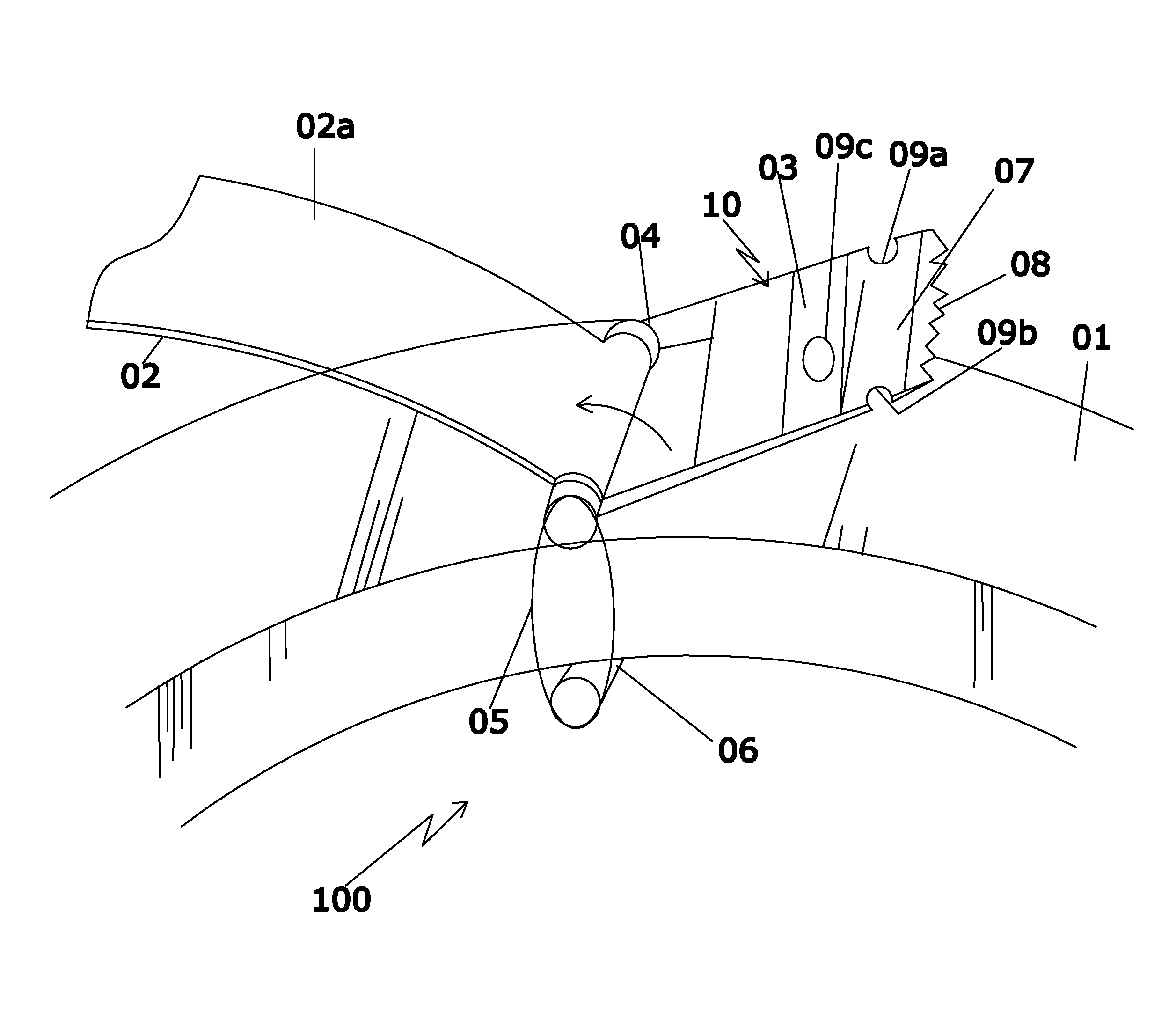
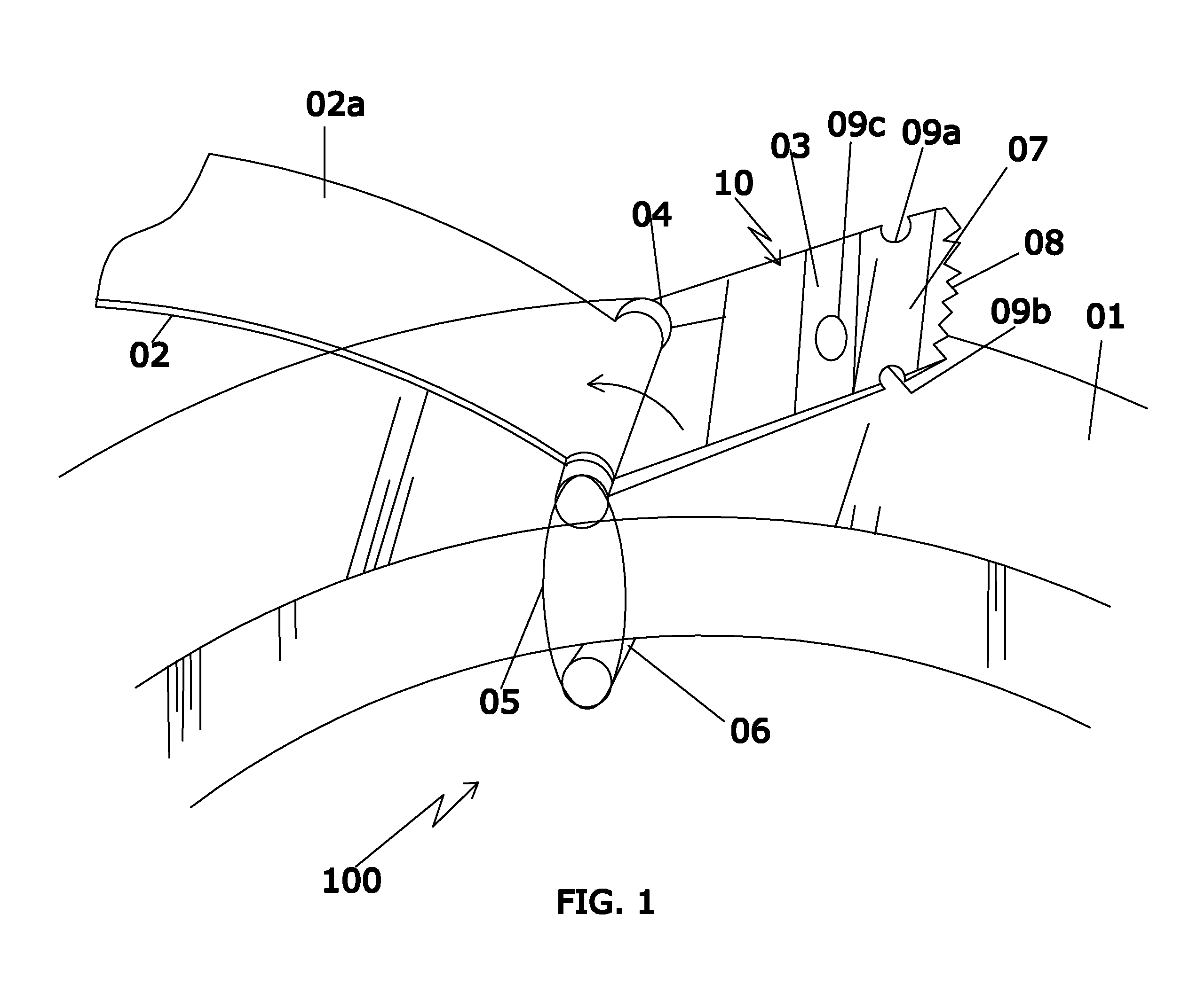
[0052]Referring to FIG. 1, an adhesive tape dispenser 100 in accordance with a preferred embodiment of the present invention is mounted on a tape roll 01. The adhesive tape dispenser 100 includ...


PUM

PropertyMeasurementUnit
lengthaaaaaaaaaa
adhesiveaaaaaaaaaa
flexibleaaaaaaaaaa

Abstract

This Dispenser having a cutter plate, which is flexibly mounted on a Tape roll, helps in peeling the Tape and is able to cut it by serration provided at the other end.There is an open space, in between the rod and cutter plate, so that Tape can be drawn over from both sides of the dispenser, to cut it by serrations present at the other end.On the cutter plate of the Dispenser, there is a notch and a hole is provided, so that, the cut end of the tape which sticks on the plate, can be easily removed for the next operation.This cutter plate assembly being flexibly attached on a Tape roll, by means of two 0 rings, can swivel like a hinge, so that Tape can be cut at any desired and from a suitable angle.A double cutter is provided to hold a firm grip on the tape, to cut it easily, besides, to protects from injury also.Thus It is a novel, Tape Dispenser which is User friendly, Multipurpose and a unique and most simple in Design, useful for most of varieties of Tapes, having variations in, Materials, Widths, Diameters, Thickness, Toughness, Stickiness, and various Applications and Uses. Most suitable for a common Man, Office, Industry and Packaging use in Industry.

Description

CROSS REFERENCE TO RELATED APPLICATION[0001]This Application Claims the benefit of provisional Patent Application Patent number Ser. no. 3144 Mumbai filed 2011 Nov. 8 by the present Inventor in IndiaFEDERALLY SPONSORED RESEARCH[0002]Not ApplicableSEQUENCE LISTING: OR PROGRAM[0003]Not Applicable[0004]This Invention relates to Adhesive Tape Dispenser which are used to dispense Tapes from various types of Tape RollsPREAMBLE TO THE DESCRIPTION[0005]The following specification particularly describes the invention and the manner in which it is to be performed.FIELD OF THE DISCLOSURE[0006]The present disclosure generally relates to a tape dispenser for dispensing a desired length of tape rolled on a tape-reel, more particularly, the present disclosure relates to a tape dispenser for dispensing a desired length of adhesive-tape from an adhesive-tape reel.BACKGROUND[0007]A tape reel includes a core in form of a roller around which an adhesive tape that has a sticky side and a glossy side is ...

Claims


Application Information

Patent Timeline
Patent Type & Authority Patents(United States)
IPC IPC(8): E04D15/00B26F3/02B44C7/00B32B38/10B29C65/00B65H35/00
CPCB65H35/0013Y10T156/1795Y10T156/1365Y10T225/257Y10T156/1788Y10T156/18Y10T225/294Y10T225/259B65H35/0026B65H35/008Y10T225/269Y10T225/268
Inventor PARKHE, DATTATRYA, PURUSHOTTAM
Owner PARKHE DATTATRAYA
Learn More