
Apparatus and method for collecting and distributing radiation

a technology of solar radiation and apparatus, applied in the direction of lighting applications, using daylight, greenhouse gas reduction, etc., can solve the problems of significant portion of available visible light wasted by shading, attenuation, and/or diffusing the dominant portion of dayligh

Active Publication Date: 2014-09-23
HERNANDEZ JORGE SIMON
View PDF45 Cites 4 Cited by
  • Summary
  • Abstract
  • Description
  • Claims
  • Application Information

AI Technical Summary

Benefits of technology

The present invention describes a system for collecting and distributing solar radiation. The system includes a lens, mirror, and a photovoltaic cell. The lens and mirror are aligned to reflect a portion of the radiation to a nonaligned lens, which focuses the radiation onto a collector target. The photovoltaic cell is movable on a track and can block or unblock the collector target. The system also includes a motor for moving the photovoltaic cell and a second lens alignedly adjacent to the mirror. The method includes collecting solar radiation, focusing it into a beam, rotating a reflective surface to redirect the beam, collecting the reflected beam with a target, and transferring it to an end fixture. The technical effect is an efficient and flexible system for collecting and distributing solar radiation.

Problems solved by technology

Eventually, however, the cost, convenience, and performance of electric lamps improved and the sun was displaced as the primary method of lighting building interiors.
In doing so, however, a significant portion of the available visible light is wasted by shading, attenuation, and / or diffusing the dominant portion of daylight, i.e. direct sunlight, which represents more than 80% of the light reaching the earth on a typical day.
Additionally, typical approaches add to building heat gain, require significant architectural modifications, and are not easily reconfigured.
Previous attempts to use sunlight directly for interior lighting via fresnel lens collectors, reflective light-pipes, and fiber-optic bundles have been plagued by significant losses in the collection and distribution system, ineffective use of non-visible solar radiation, and a lack of integration with co-located electric lighting systems required to supplement solar lighting on cloudy days and at night.
Electrical power wiring needed to be run from the main utility power supply, thus creating a labor intensive installation process.
Running, burying, and connecting electric wire cable is time consuming and requires specialized and skilled labor.
The traditional trade-off between night-time illumination energy required and daytime solar energy collected has precluded using only solar energy and has forced inventors to also use main utility power with its inherent complexities of installation.

Method used


Image

  • Apparatus and method for collecting and distributing radiation
  • Apparatus and method for collecting and distributing radiation
  • Apparatus and method for collecting and distributing radiation

Examples


Embodiment Construction

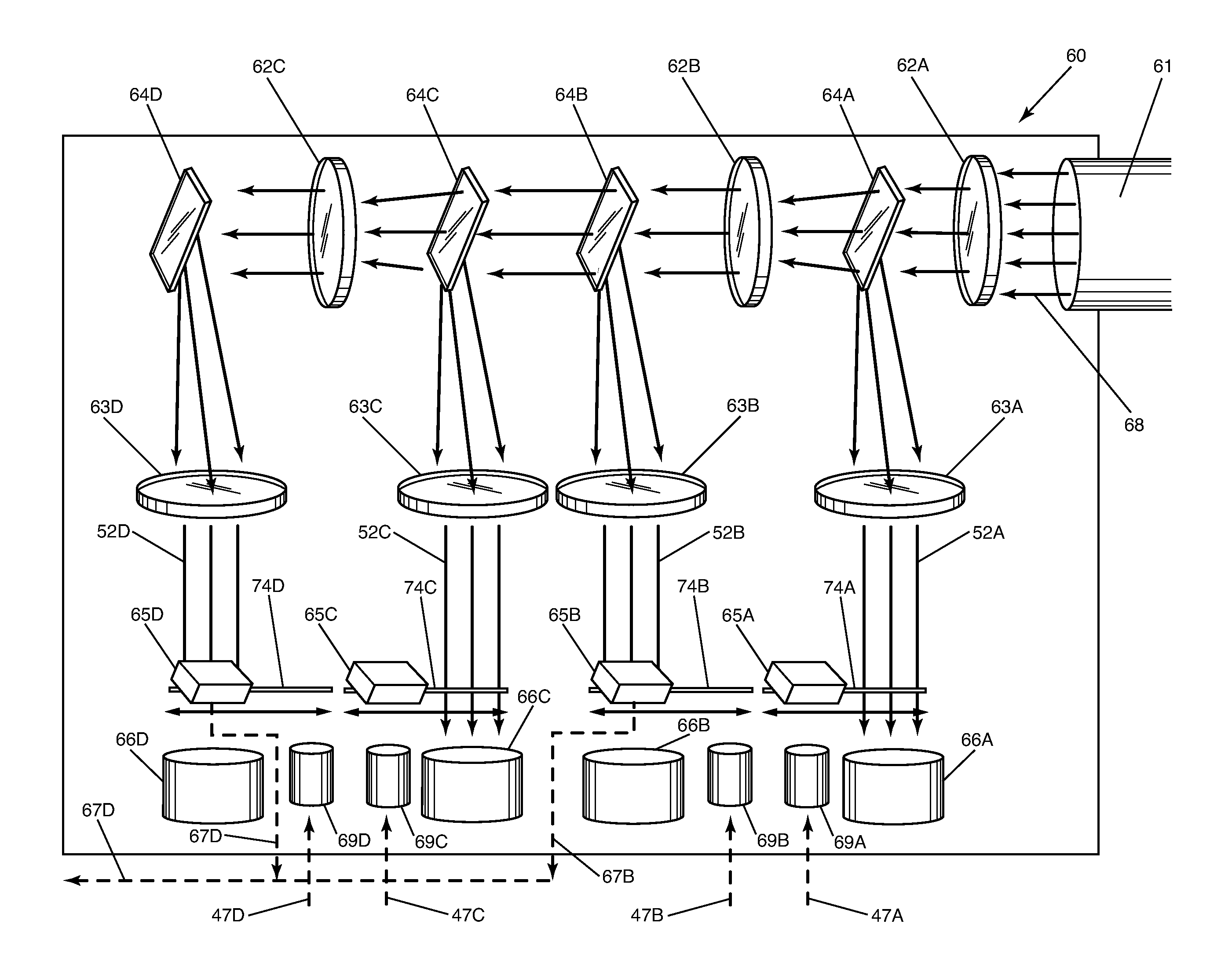
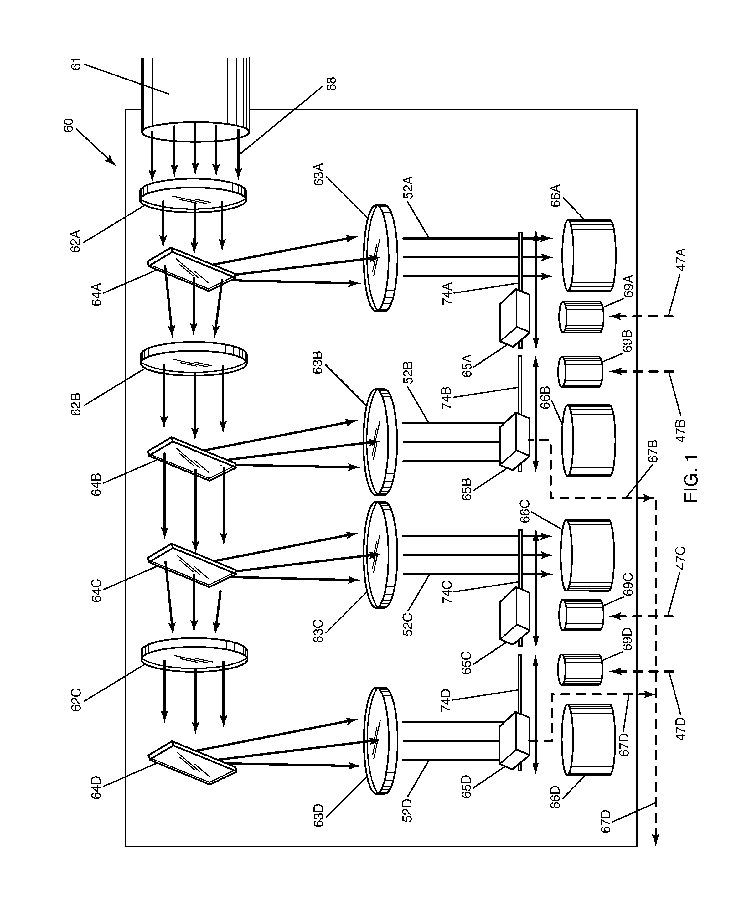
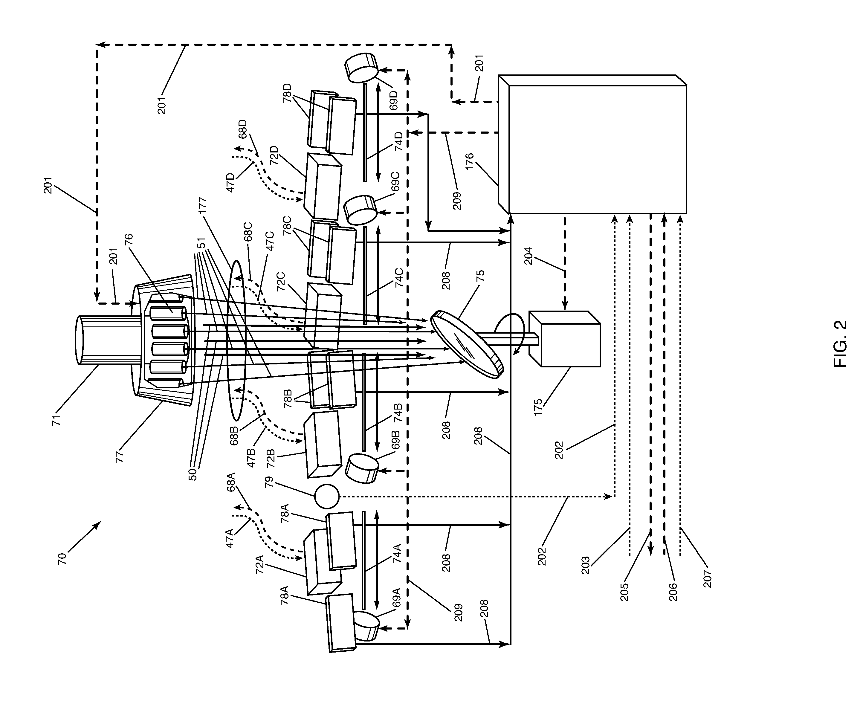
[0014]The present invention is directed to a solar radiation collection and distribution system comprising an input fiber optic cable, a lens disposed alignedly adjacent to said cable, a mirror disposed alignedly adjacent to said lens for reflecting a portion of radiation to a second nonaligned lens, wherein said second lens focuses the radiation, a photovoltaic cell movably disposed on a track and a collector target comprising a fiber optic cable.

[0015]The solar radiation collection and distribution system further comprises a motor that provides the power needed to move the photovoltaic cell back and forward along the track, in order to adjust the placement of the photovoltaic cell at any point along the track. The photovoltaic cell is movably disposed on the track to obstruct said collector target and alternately to provide radiation to the collector target.

[0016]The system further comprises a second lens disposed alignedly adjacent to the mirror and a second mirror disposed align...


PUM


Abstract

The present invention provides for a hybrid solar radiation collection and distribution system comprising both passive solar and active solar components, generating electric potential, generating heat, and distributing visible light to numerous endpoints.

Description

CROSS-REFERENCE TO RELATED APPLICATIONS[0001]This application claims priority to and the benefit of the filing of U.S. Provisional Patent Application Ser. No. 61 / 228,446, entitled “Apparatus and Method for Collecting and Distributing Radiation”, filed on Jul. 24, 2009, and the specification thereof is incorporated herein by reference.BACKGROUND OF THE INVENTION[0002]1. Field of the Invention (Technical Field)[0003]The present invention relates to an apparatus and method for collecting, transmitting, and distributing solar radiation to the interior of structures or to exterior facilities.[0004]2. Description of Related Art[0005]Currently, there is a need for inexpensive, efficient lighting for structures and facilities, using solar energy.[0006]Throughout the 20th century, use of the sun as a source of energy has evolved considerably. The sun was the primary source of interior lighting for buildings during the day prior to the 20th century. Eventually, however, the cost, convenience,...

Claims


Application Information

Patent Timeline
Patent Type & Authority Patents(United States)
IPC IPC(8): F24J2/38F21S11/00F21S19/00F24S23/00F24S23/30F24S23/77F24S50/20H01L31/052H01L31/053
CPCY02E10/40F24J2/08Y02E10/52H01L31/0522F24J2/067F24J2/16F21S11/00H01L31/0586F21S19/005H02S40/38H01L31/0547H01L31/0525H01L31/054H01L31/0543F24S21/00F24S23/12F24S23/30F24S23/77Y02E70/30
Inventor HERNANDEZ, JORGE, SIMON
Owner HERNANDEZ JORGE SIMON
Learn More