
Lingual orthodontic appliance with removable section

a lingual, removable technology, applied in the field of aesthetic orthodontic appliances, can solve the problems of inability to correct particular dental malocclusions, inability to extrude, gap closure, and inability to achieve molar teeth movement, etc., to achieve controllable and secure connection, improve oral hygiene, and facilitate disconnection

Inactive Publication Date: 2014-09-09
3M INNOVATIVE PROPERTIES CO
View PDF35 Cites 54 Cited by
  • Summary
  • Abstract
  • Description
  • Claims
  • Application Information

AI Technical Summary

Benefits of technology

The present invention is an aesthetic and effective orthodontic appliance that can be easily removed. It controls the movement of teeth in a way that is similar to fixed appliances, but it is partially removable. This appliance allows for improved oral hygiene and provides a secure and controlled connection to the teeth, but it can also be easily disconnected.

Problems solved by technology

Polymeric shells, for example, tend to be limited in their ability to correct particular dental malocclusions.
Extrusion, gap closure, and molar teeth movement can be difficult or impossible to achieve, since these appliances rely on relatively weak mechanical retention between the shell and the teeth.
Moreover, polymeric aligners are not entirely aesthetic even when clear, since they still cover the facial teeth surfaces and can stain or trap dark liquids such as coffee.
On the other hand, retainer-like appliances that use springs or clasps that engage with teeth suffer from many of the same shortcomings as polymeric aligners.
These appliances, as a whole, do not positively engage with the teeth in a manner that allows precise torque, angulation, rotational, and translational control.
Further, many of these devices are generally not aesthetic since they use a facial wire residing over the facial surface of the teeth to prevent proclination of the teeth.
Even more significantly, none of the above appliances are capable of controlling the forces directed to each individual tooth using anchorage from a portion of the dental structure, such as the palate, that does not change during treatment.

Method used


Image

  • Lingual orthodontic appliance with removable section
  • Lingual orthodontic appliance with removable section
  • Lingual orthodontic appliance with removable section

Examples


Embodiment Construction

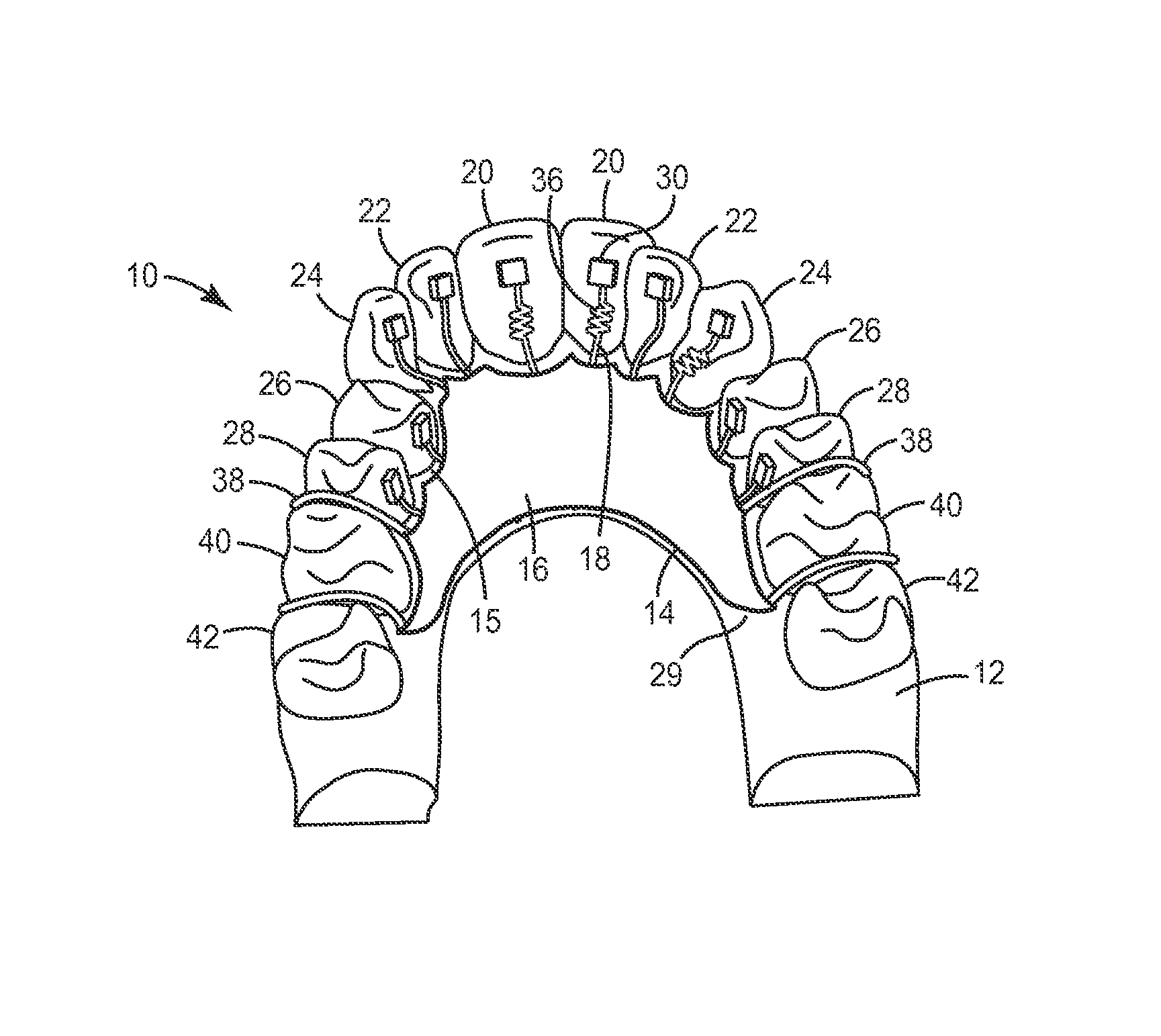
[0031]The present invention is directed to lingual appliances that are customized to the patient, at least partially removable, and may be used to retain, or alternatively change the position of, one or more teeth of the upper or lower dental arch. An exemplary appliance in accordance with one embodiment of the invention is shown for the upper dental arch in FIGS. 1 and 2, and is broadly designated by the numeral 10. Upper arch appliance 10 includes a removable section 14 along with a plurality of corresponding anchors 48 (not visible in FIG. 1) that are, in turn, connected to the lingual tooth surfaces of a physical dental model 12. Dental model 12, which may be constructed of orthodontic stone (plaster of Paris) or epoxy resin, is a positive replica of a patient's upper central 20, lateral 22, cuspid 24, first bicuspid 26, second bicuspid 28, first molar 40, and second molar 42 teeth, as well as gingiva and lingual soft tissues collectively designated 29. Depending on the patient,...


PUM

PropertyMeasurementUnit
magnetic couplingsaaaaaaaaaa
flexibleaaaaaaaaaa
areaaaaaaaaaaa

Abstract

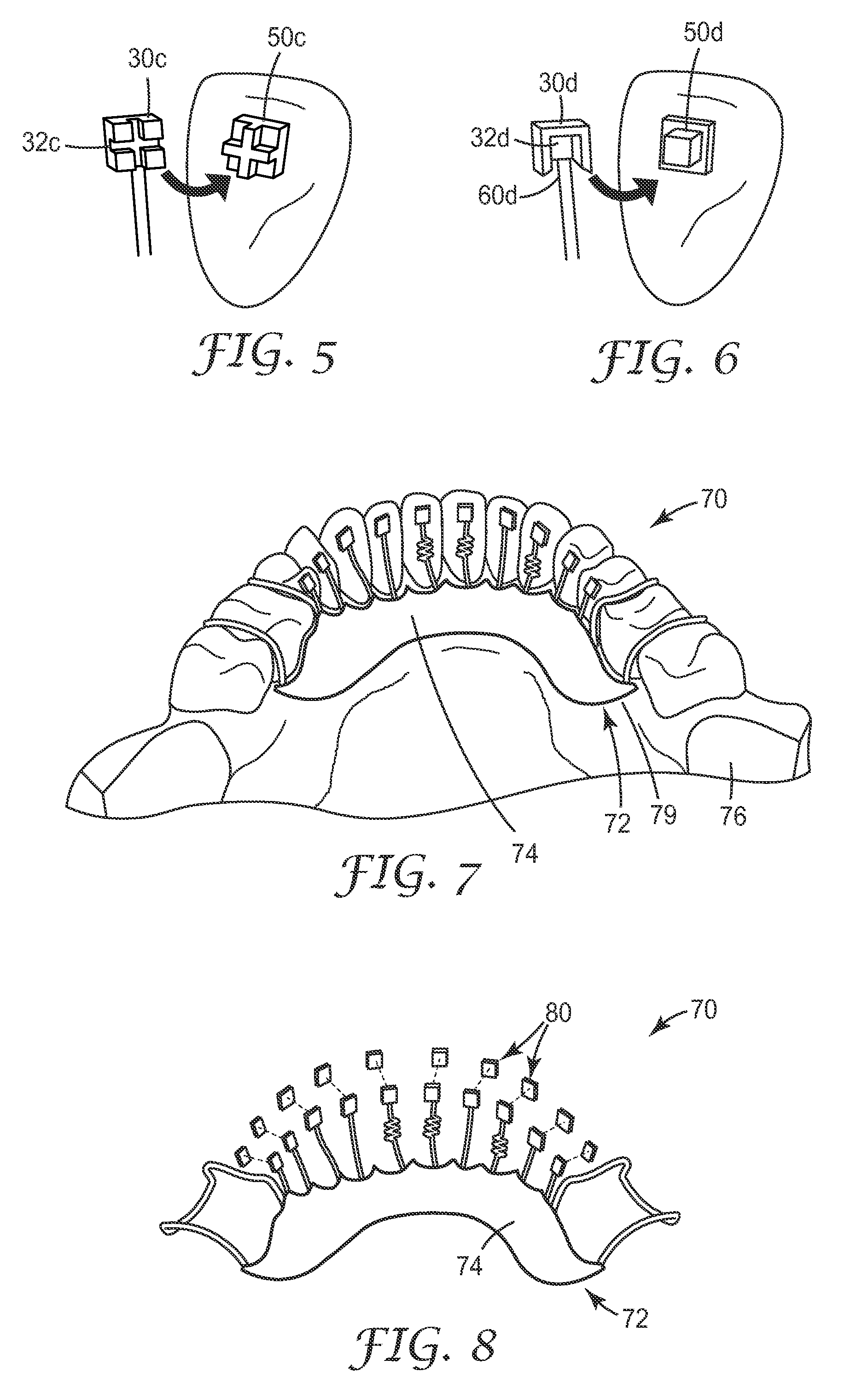
An aesthetic, partially removable orthodontic appliance is described, including a polymeric body that conforms to the lingual soft tissue and at least one wire member extending from the polymeric body. Each wire member releasably engages with a respective anchor that is, in turn, connected to the lingual surface of a respective tooth when the polymeric body is moved in a generally gingival direction into abutting relationship with the lingual soft tissue. Other features of the appliance include self-guiding magnetic couplings and couplings based on interlocking mechanical structures that provide releasable engagement between the removable section and the anchors, as well as related methods for making and using the same.

Description

CROSS REFERENCE TO RELATED APPLICATIONS[0001]This application is a national stage filing under 35 U.S.C. 371 of PCT / US2009 / 038157, filed Mar. 25, 2009, which claims priority to Provisional Application No. 61 / 043,495, filed Apr. 9, 2008, the disclosure of which is incorporated by reference in its / their entirety herein.BACKGROUND OF THE INVENTION[0002]1. Field of the Invention[0003]This invention broadly pertains to an appliance used in orthodontic treatment. More particularly, it pertains to an aesthetic orthodontic appliance that is at least partially removable.[0004]2. Description of the Related Art[0005]Orthodontics is the area and specialty of dentistry associated with the supervision, guidance, and correction malpositioned teeth into proper locations. Orthodontic treatment can be useful in correcting defects in a patient's bite (also called occlusion) along with promoting better hygiene and improving the overall aesthetics and health of the teeth.[0006]Orthodontic treatment ofte...

Claims


Application Information

Patent Timeline
Patent Type & Authority Patents(United States)
IPC IPC(8): A61C3/00A61C7/00A61C7/10A61C7/14
CPCA61C7/10A61C7/145A61C7/006Y10T29/49568A61C7/30A61C7/08A61C7/06
Inventor CINADER, JR., DAVID K.SOO, PHILIP P.CLEARY, JAMES D.PUTTLER, OLIVER L.
Owner 3M INNOVATIVE PROPERTIES CO
Learn More