
Horizontal ducted wind turbine

a ducted wind turbine and horizontal technology, applied in the direction of motors, electrical devices, control systems, etc., can solve the problems of diminishing supply, reducing supply, and generating waste that can be harmful to the environment, so as to facilitate stabilization positioning and maximize wind velocity

Inactive Publication Date: 2014-09-02
AL WASIS ADEL A
View PDF15 Cites 11 Cited by
  • Summary
  • Abstract
  • Description
  • Claims
  • Application Information

AI Technical Summary

Benefits of technology

The patent describes a wind turbine that includes a power generator mounted on a pole, a wind funnel that helps focus wind onto the turbine, and a turbine inside the funnel that produces energy as it spins. The wind funnel can be adjusted to face the wind direction and has wings to make it easier to position and adjust itself as the wind changes. The technical effect of the patent is a wind turbine that can capture more wind energy and produce more energy efficiently.

Problems solved by technology

However, the conventional systems also produce wastes that can be harmful to the environment if active steps have not been taken to regulate or check handling and disposal of the same.
Moreover, the world does not contain an infinite supply of fuels such as fossil fuel and coal.
At the rate of current consumption, this diminishing supply may not be able to meet future demands.
As for nuclear power, much expense must be expended to construct the fuel rods, and when spent, the disposal thereof requires careful handling and disposal in special sites built to contain the radiation from residual radioactive materials that can last for centuries.
However, the solar panels typically used in solar power energy systems can be relatively expensive for relatively low efficient energy conversion, though improvements in efficiency are continuously being made.
Moreover, the costs for space and maintenance of such solar panels can be relatively expensive, diminishing the potential profits that can be gained thereby.
While sufficient, a single generator necessarily limits the amount of power that can be generated from the wind blowing past the propellers.
Such considerations and designs ultimately increase costs, and due to the nature of these types of systems, relatively large tracts of land typically would be required to produce energy for consumption by a given population.
Such systems tend to be bulky and not aerodynamic, which decreases efficient utilization of the incoming wind.

Method used


Image

  • Horizontal ducted wind turbine
  • Horizontal ducted wind turbine
  • Horizontal ducted wind turbine

Examples


Embodiment Construction

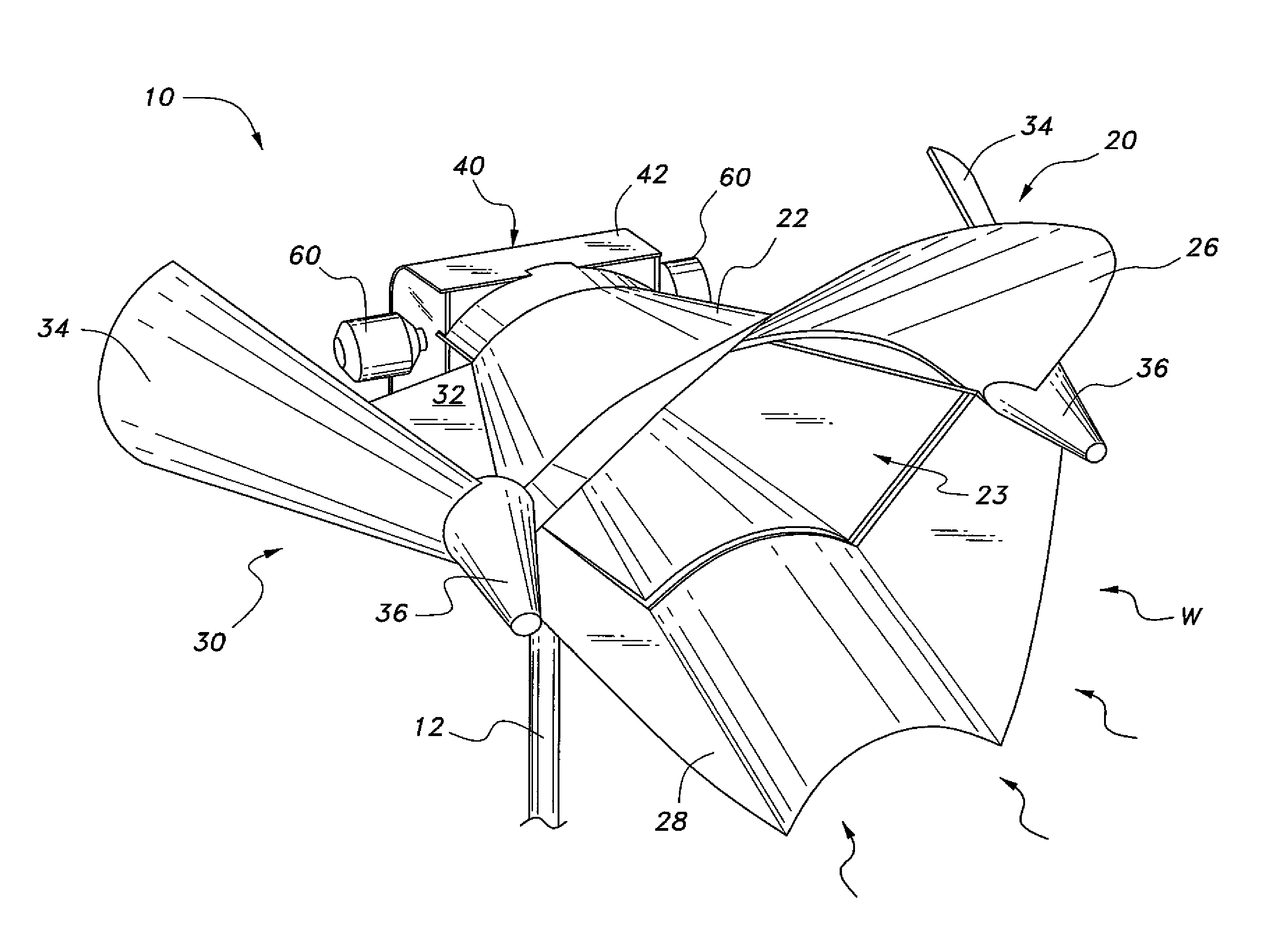
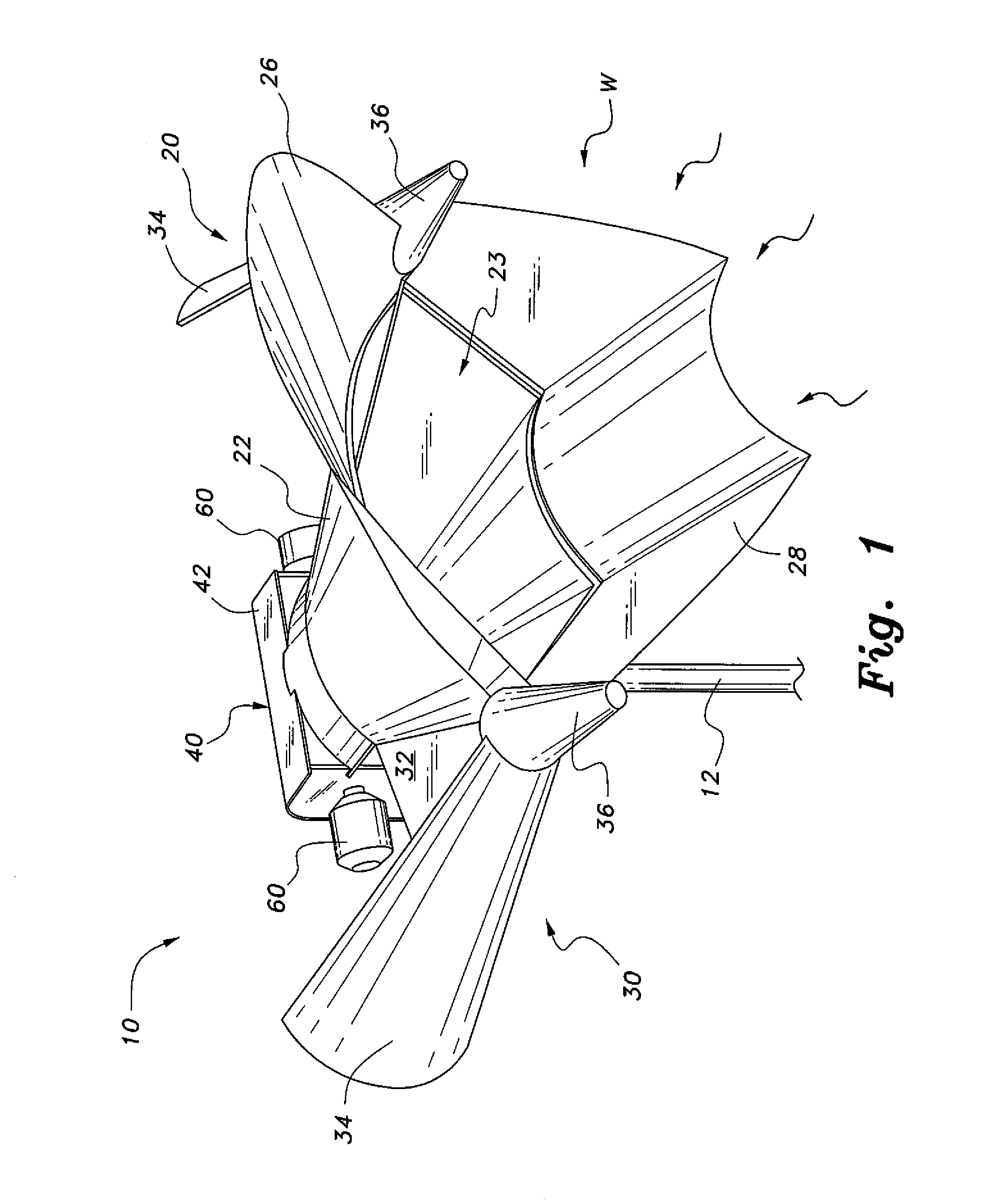
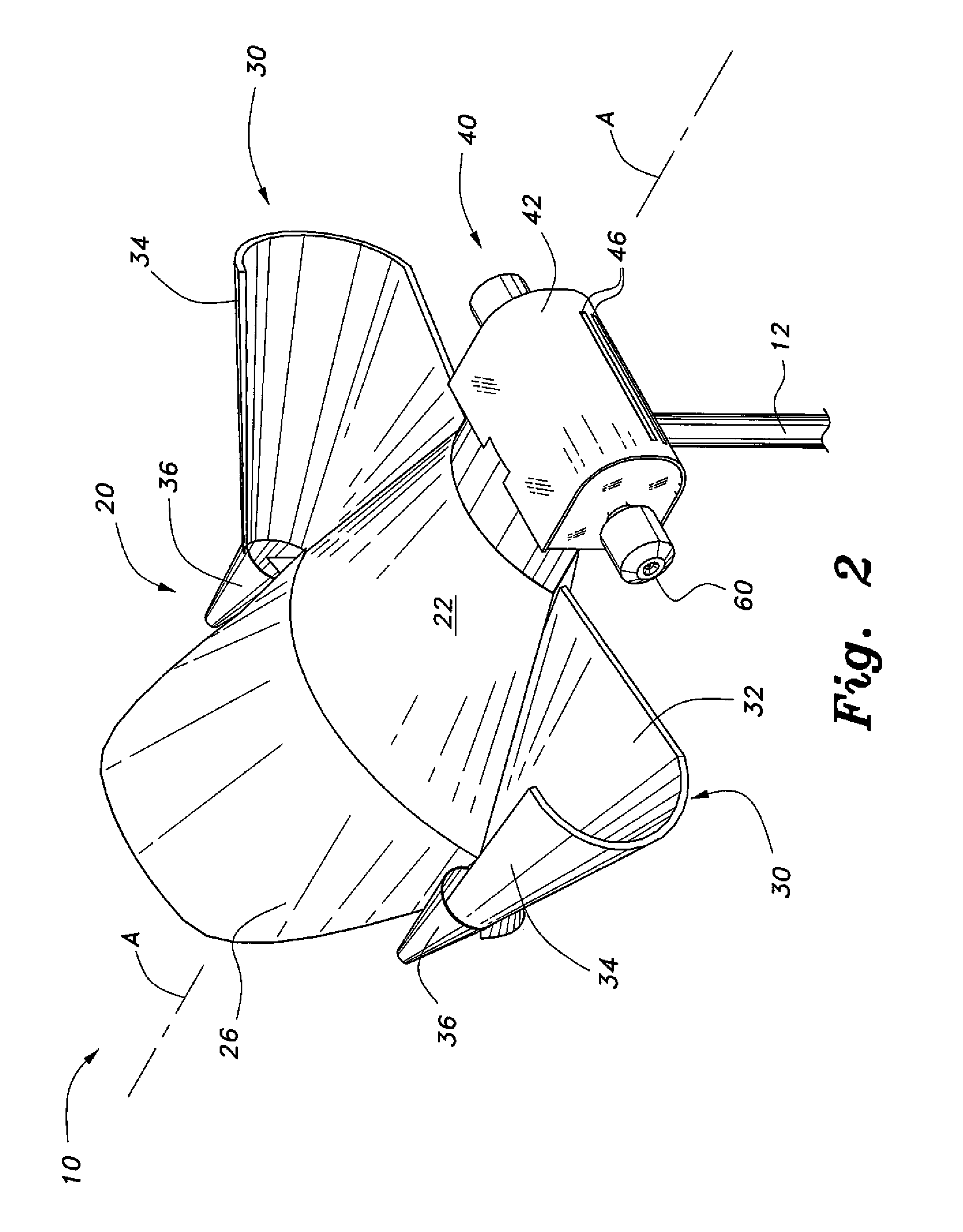
[0020]The horizontal ducted wind turbine, a first embodiment of which is designated by the reference number 10, provides efficient generation of power with maximal conversion of wind power. As shown in FIGS. 1-3, the horizontal ducted wind turbine 10 includes a wind funnel assembly 20 detachably mounted to a power generator assembly 40. The wind funnel assembly 20 passively compresses incoming wind as the wind passes through so that the exit velocity of the wind is relatively high prior to entering the power generator assembly 40. The relatively high velocity of the exiting wind turns a turbine 50 in the power generator assembly 40 in order to convert the same into useable energy such as electricity. The synergy between compressed wind flow and the effect thereof on the power generator assembly 40 maximizes use of the potential energy contained in the incoming wind at any given entering velocity, which can result in a more efficient wind power generation system.

[0021]Referring back ...


PUM


Abstract

The horizontal ducted wind turbine includes a power generator assembly adapted to be rotatably mounted to an elongate pole. At least one wind funnel assembly extends from one side of the power generator assembly. The wind funnel assembly includes an elongate funnel with a relatively large inlet at one end and a relatively small outlet at the opposite end in communication with a housing of the power generator assembly. A turbine is rotatably mounted inside the housing and a pair of generators is disposed on opposite ends of the turbine. The funnel passively compresses incoming wind to maximize wind velocity acting on the turbine to rotate the same causing the generator to produce energy. The wind funnel assembly can be provided with wings that facilitate stabilized positioning and self-orienting in response to changes in wind direction.

Description

BACKGROUND OF THE INVENTION[0001]1. Field of the Invention[0002]The present invention relates to alternative energy systems, and particularly to a horizontal ducted wind turbine with features for maximizing power generation.[0003]2. Description of the Related Art[0004]Currently, alternative energy has become a major focus worldwide. The conventional energy systems that use sources such as fossil fuel, coal, and nuclear power produce much, if not most, of the energy consumed on a daily basis. However, the conventional systems also produce wastes that can be harmful to the environment if active steps have not been taken to regulate or check handling and disposal of the same. Moreover, the world does not contain an infinite supply of fuels such as fossil fuel and coal. At the rate of current consumption, this diminishing supply may not be able to meet future demands. As for nuclear power, much expense must be expended to construct the fuel rods, and when spent, the disposal thereof req...

Claims


Application Information

Patent Timeline
IPC IPC(8): F03D9/00H02P9/04F03D3/00F03D3/04
CPCF03D3/0427F03D9/002F05B2240/133F03D3/002Y02E10/74F03D9/25
Inventor AL-WASIS, ADEL, A.
Owner AL WASIS ADEL A
Learn More