
Apparatus and method for decoding digital image and audio signals

a digital image and audio signal technology, applied in the field of encoding digital and audio images, can solve the problems of high cost of making a large number of film duplicates, inability to provide high fidelity multi-channel audio programming, and inherent limitations, and achieve the effect of flexible and cost-efficient presentation options

Inactive Publication Date: 2014-08-19
QUALCOMM INC
View PDF122 Cites 1 Cited by
  • Summary
  • Abstract
  • Description
  • Claims
  • Application Information

AI Technical Summary

Benefits of technology

The patent text describes the role of a theater manager in controlling various aspects of projection operations, including storage, decompression, decryption, and display of programming material. The theater manager may also control the playback period and number of play backs. The use of digital encryption provides a built-in security measure. Physical security measures may also be used to protect the programming material. The patent also mentions the possibility of integrating projection operations with other theater operations and the use of multiple auditorium modules for flexible and cost-efficient presentation options.

Problems solved by technology

Although the distribution process shown in FIG. 1 works well, there are inherent limitations.
Due to the use of celluloid material for the film and the bandwidth limitations of the film media, there are restrictions on the ability to provide high fidelity multi-channel audio programming.
Then, there is the high expense of making a large number of film duplicates, which can cost several hundreds of dollars for each feature length film.
There is also the expense, complexity, and delay associated with physically distributing large canisters of celluloid film to a large and growing number of theater locations.
Because of the large number of duplicates made, it becomes increasingly difficult to prevent illegal duplication and theft of the material.
It is estimated that revenues lost due to piracy and theft account for billions of dollars lost each year by the motion picture industry.
Further, duplicated film material tends to degrade over time due to dust collection, wear-and-tear, thermal variances, and other known factors.
Finally, management cost and other expenses are involved in the eventual destruction of the film material, which may contain regulated hazardous material.
For example, satellite transmission methods are now available, although they are not currently commercially viable for the distribution of high quality audio / visual (AV) material.
This high data rate requires the capacity equivalent of an entire satellite to transmit even a single program, which is prohibitively expensive.
Moreover, alternative distribution technologies have not been able to offer the image quality and projection brightness available using celluloid film.
These technologies do not offer the quality of film due to bandwidth limitations.
Moreover, implementation of a satellite based transmission and receiver system is costly and a radical change from current methods of film distribution and display.
It is perceived that such a radical change may not be initially commercially acceptable.
Although some DVD-ROM devices exist advertise an 8 MB / sec transfer rate, the quality and reliability of such devices is unknown.
Thus, there is no guarantee that such DVD-ROM devices can reliably sustain a 6 MB / sec transfer rate.
Distribution of film information using a digital electronic format actually increases the potential for rapid, low-cost duplication without quality degradation.
However, along with the “ease of duplication” associated with digital technology, there exists encryption techniques to ensure that the information is encoded in a way that prevents useful information from being distributed to unauthorized parties.
However, a complete digital cinema system has not been developed by the motion picture industry or related arts.
Several issues and problems remain to be solved.
Theater complexes with multiple auditoriums have grown larger in an effort to provide a greater economic return, resulting in more complicated presentation schedules, and a larger number of locations showing a given film.
This could require many additional electronic copies to be forwarded to theaters for presentation using current techniques, with associated complexity and operating costs.

Method used


Image

  • Apparatus and method for decoding digital image and audio signals
  • Apparatus and method for decoding digital image and audio signals
  • Apparatus and method for decoding digital image and audio signals

Examples


Embodiment Construction

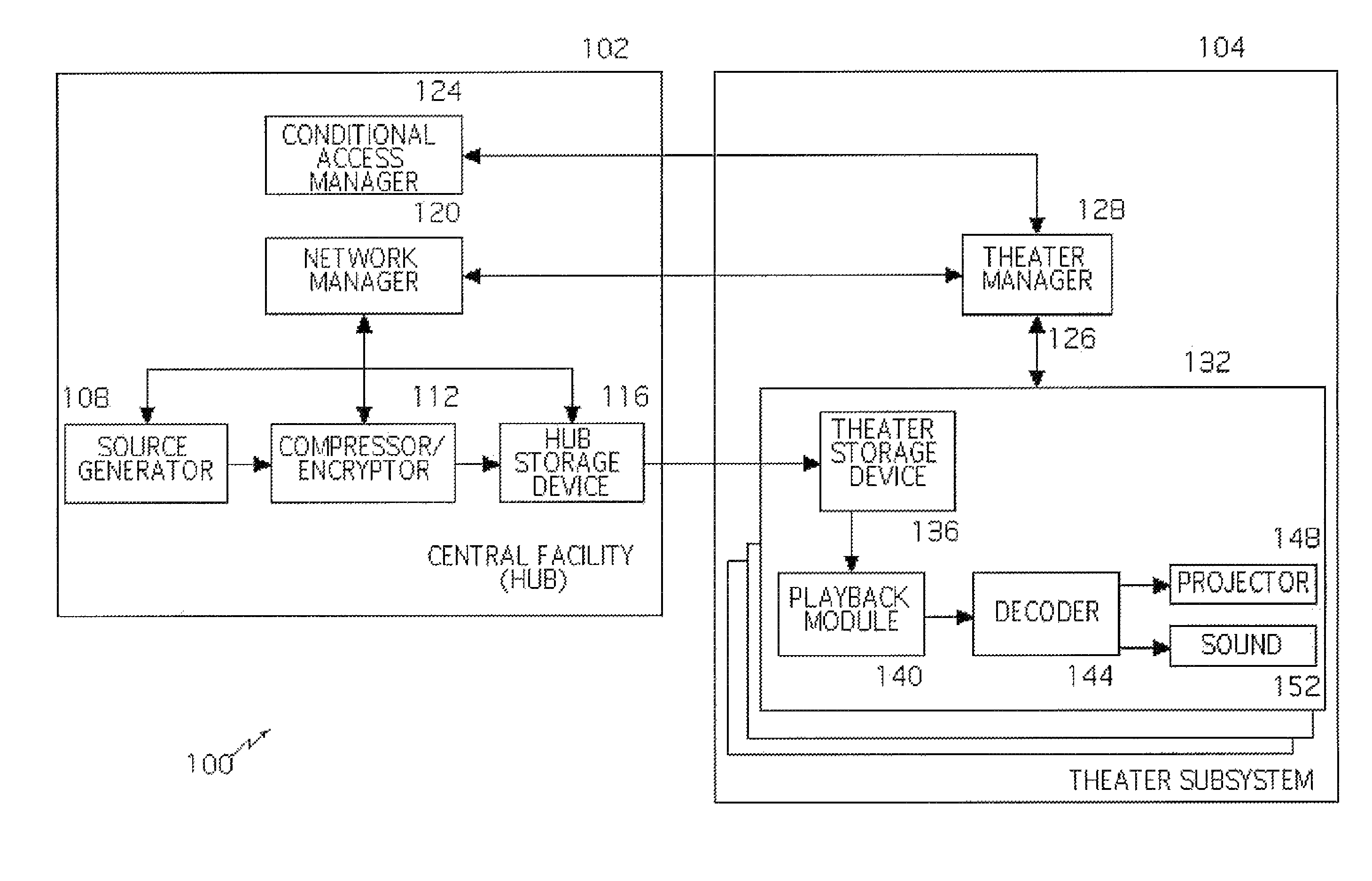
[0050]The present invention comprises an apparatus and method, sometimes referred to herein as “digital cinema”, for the electronic decoding, decompression and decryption of audio / visual programming, such as motion pictures in theater systems, theaters, theater complexes, and / or presentation systems.

[0051]Digital cinema incorporates innovation in image and audio compression, projection technology, encryption methodology, and many other areas. Digital cinema is designed to replace the current method of physical distribution of celluloid film to each play back or projection location such as theaters or remote auditoriums. Digital cinema eliminates the need for duplication of celluloid film, and offers the potential for exceptional audio / visual quality as well as built-in security measures. Programs may be transmitted to theaters and stored on storage devices, such as removable hard drives (RHD) or digital versatile disks (DVD), for display at later times.

[0052]While the invention is e...


PUM

PropertyMeasurementUnit
timeaaaaaaaaaa
presentation timeaaaaaaaaaa
areaaaaaaaaaaa

Abstract

An apparatus and method for decoding of encoded signals representing at least image information from a storage medium is claimed. A storage device is configured to receive the storage medium. A decoder is configured receive the compressed encrypted encoded signals from the storage medium, and send the signals to a decryptor. The decryptor is configured to decrypt the compressed encrypted encoded signals, and send the signals to a decompressor. The decompressor is configured to receive the compressed encoded signals from the decryptor and to decompress the compressed encoded signals to enable display of the image.

Description

CROSS-REFERENCE TO RELATED APPLICATIONS[0001]This application is a continuation-in-part of, and claims the benefit of priority from, co-pending U.S. patent application Ser. No. 09 / 075,152, entitled “Apparatus and Method for Distribution of High Quality Image and Audio Programs to Remote Locations” and filed on May 8, 1998, which is assigned to the same assignee as this application and is fully incorporated herein by reference for all purposes.[0002]This application also a continuation of, and claims the benefit of priority from, co-pending U.S. patent application Ser. No. 09 / 563,880, entitled “Apparatus and Method for Decoding Digital Image and Audio Signals” and filed on May 3, 2000, which claims the benefit of priority from U.S. Provisional Patent Application Ser. No. 60 / 168,605, entitled “Apparatus and Method for Distribution and Viewing of High Quality Image and Audio Programs to Remote Locations” and filed on Dec. 2, 1999, both of which are assigned to the same assignee as this...

Claims


Application Information

Patent Timeline
Patent Type & Authority Patents(United States)
IPC IPC(8): H04N7/64H04N21/41H04N21/4623H04N21/432H04N21/214G11B20/00H04N21/222H04N21/418H04N21/266H04N21/4627H04N7/16H04N21/4405H04N7/167H04N9/31H04N21/231H04N19/89H04N7/18H04N21/414H04N5/913H04N21/442G11B20/10H04N21/226
CPCG11B20/00507H04N21/41415G11B20/00007H04N21/2265H04N21/23116H04N21/4181H04N7/163H04N21/4623G11B20/00086H04N7/167H04N7/165H04N21/2143H04N9/31H04N21/4627G11B20/00673H04N21/44204H04N21/26613G11B20/0021H04N21/4131H04N21/4325H04N21/4405H04N21/222H04N5/913H04N7/1675H04N2005/91364G11B2020/10537G11B2020/10638G11B2220/2516G11B2220/2562
Inventor MORLEY, STEVEN A.FAUS, JUANRATZEL, JOHN
Owner QUALCOMM INC
Learn More