Junction box and solar cell array
- Summary
- Abstract
- Description
- Claims
- Application Information
AI Technical Summary
Benefits of technology
Problems solved by technology
Method used
Image
Examples
Embodiment Construction
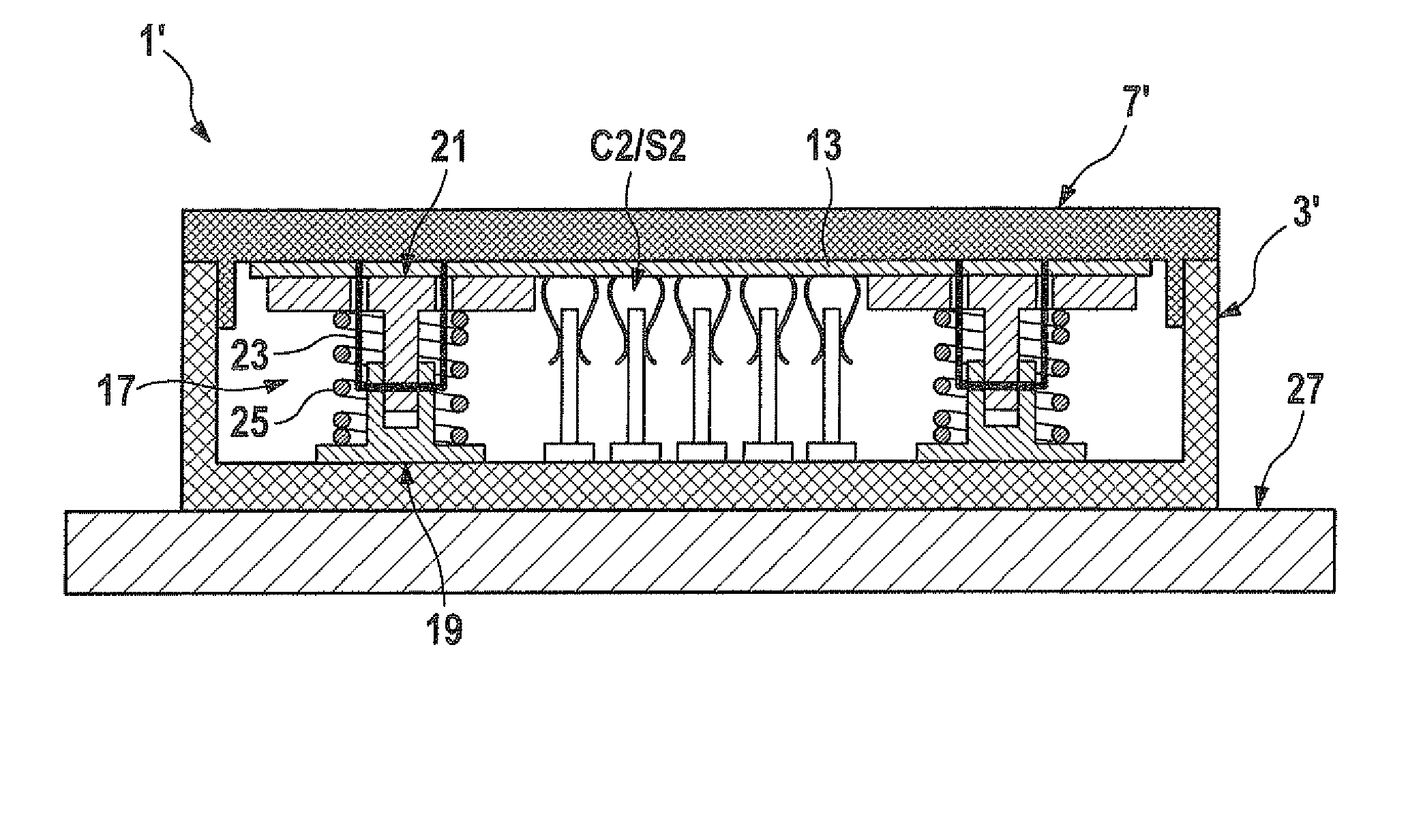
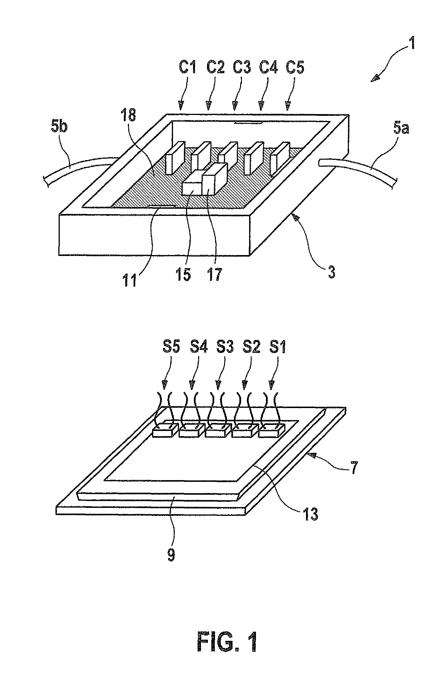
[0021]FIG. 1 shows a simplified perspective illustration of the parts of a junction box 1 of a solar cell module, namely a bottom part (base body) 3 having connecting cables 5a and 5b and a top part (cover) 7. A peripheral set-back frame 9 on the inside of top part 7 has an undercut edge, so that when the top part is placed on the bottom part, the box is locked in place as soon as the correspondingly shaped (or inserted) protrusions 11 on the top edge of the inside wall of bottom part 3 engage.
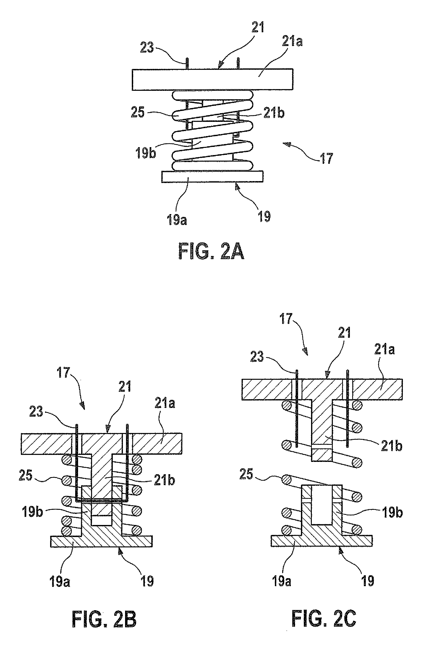
[0022]Bottom part 3 shows a group of first contact arrangement C1 through C5, while second contact arrangement S1 through S5 are situated in corresponding positions thereto protruding perpendicularly from the inside of top part 7. In the embodiment shown here, first contact arrangement C1 through C5 have essentially a flat cuboid-shape and second contact arrangement S1 through S5 are each formed from a carrier section (not shown in detail) and an omega-shaped contact spring arising out of the ...
PUM
 Abstract
Description
Claims
Application Information
 - R&D
- Intellectual Property
- Life Sciences
- Materials
- Tech Scout
- Unparalleled Data Quality
- Higher Quality Content
- 60% Fewer Hallucinations
Browse by: Latest US Patents, China's latest patents, Technical Efficacy Thesaurus, Application Domain, Technology Topic, Popular Technical Reports.
© 2025 PatSnap. All rights reserved.Legal|Privacy policy|Modern Slavery Act Transparency Statement|Sitemap|About US| Contact US: help@patsnap.com


