
Parylene-based microelectrode array implant for spinal cord stimulation

a microelectrode array and spinal cord technology, applied in the field of implantable electrode arrays, can solve the problem that none of these designs has been successfully implanted chronically

Active Publication Date: 2014-08-12
RGT UNIV OF CALIFORNIA +2
View PDF10 Cites 41 Cited by
  • Summary
  • Abstract
  • Description
  • Claims
  • Application Information

AI Technical Summary

Benefits of technology

This patent describes a system that includes a stimulation generator, an implantable electrode array assembly, a baseplate, and several wires. The system is designed to generate electrical stimulation and provide it to the spinal column through the implantable electrode array assembly. The baseplate connects to the spinal column and is responsible for conducting the electrical stimulation to the assembly. The wires connect the baseplate and the stimulation generator, and they are designed to safely deliver the stimulation to the assembly. Additionally, the system may have an overhanging portion that protects the assembly from external tissue movements. The technical effects of this patent are improved delivery of electrical stimulation to the spinal column for pain management and other applications.

Problems solved by technology

The publications cited above and other work has led to various designs for high-density electrode arrays to further research, but unfortunately none of these designs has been successfully implanted chronically.

Method used


Image

  • Parylene-based microelectrode array implant for spinal cord stimulation
  • Parylene-based microelectrode array implant for spinal cord stimulation
  • Parylene-based microelectrode array implant for spinal cord stimulation

Examples


Embodiment Construction

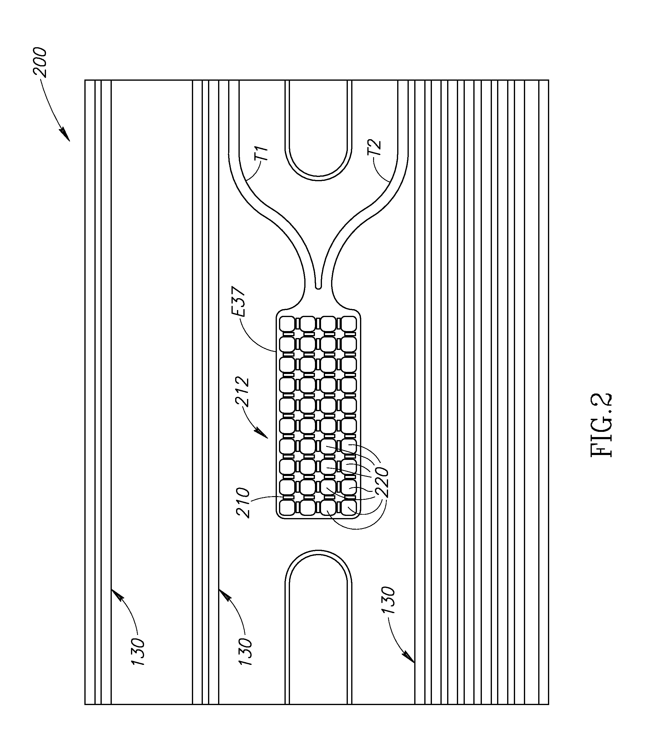
[0031]FIG. 1 illustrates an implantable electrode array assembly 100. While the embodiment of the assembly 100 illustrated is configured for implantation in a rat 500 (see FIG. 5A), embodiments may be constructed for use in other subjects, such as other mammals, including humans, and such embodiments are within the scope of the present teachings. The assembly 100 is for use with a subject that has a spinal cord 330 (see FIG. 3) with at least one selected spinal circuit (not shown) and a neurologically derived paralysis in a portion of the subject's body. By way of a non-limiting example, the assembly 100 may be implanted epidurally along the spinal cord 330. The assembly 100 may be positioned at one or more of a lumbosacral region, a cervical region, and a thoracic region of the spinal cord 330.

[0032]By way of non-limiting examples, when activated, the selected spinal circuit may (a) enable voluntary movement of muscles involved in at least one of standing, stepping, reaching, grasp...


PUM


Abstract

An implantable electrode array assembly configured to apply electrical stimulation to the spinal cord. A substantially electrically nonconductive layer of the device has a first portion positionable alongside the spinal cord that includes a plurality of first openings and a second portion that includes a plurality of second openings. Electrodes and traces are positioned inside a peripheral portion of a body portion of the device and alongside the layer. At least one of the first openings is adjacent each of the electrodes to provide a pathway through which the electrode may provide electrical stimulation to the spinal cord. At least one of the second openings is adjacent each of the traces to provide a pathway through which the trace may receive electrical stimulation. At least one trace is connected to each electrode and configured to conduct electrical stimulation received by the trace(s) to the electrode.

Description

CROSS REFERENCE TO RELATED APPLICATION(S)[0001]This application is a continuation of International Application PCT / US2012 / 22257, filed Jan. 23, 2012, and that International Application was published under PCT Article 21(2) in English. This application also claims the benefit of U.S. Provisional Application No. 61 / 435,188, filed Jan. 21, 2011, which is incorporated herein by reference in its entirety.STATEMENT REGARDING FEDERALLY SPONSORED RESEARCH OR DEVELOPMENT[0002]This invention was made with Government support under Grant No. W81XWH-09-2-0024, awarded by the United States Army, Medical Research and Materiel Command; and Grant No. EB076151, awarded by the National Institutes of Health. The Government has certain rights in this invention.BACKGROUND OF THE INVENTION[0003]1. Field of the Invention[0004]The present invention is directed generally to implantable electrode arrays, and more particularly to implantable electrode arrays used to deliver electrical stimulation to the spinal...

Claims


Application Information

Patent Timeline
Patent Type & Authority Patents(United States)
IPC IPC(8): A61N1/05
CPCA61N1/0551A61N1/0558A61N1/0553A61N1/36062A61N1/36067A61N1/36128A61N1/375H01B5/14A61B2562/125A61B5/24
Inventor TAI, YU-CHONGNANDRA, MANDHEEREJ S.BURDICK, JOEL W.RODGER, DAMIEN CRAIGFONG, ANDYEDGERTON, VICTOR REGGIEROY, ROLAND R.GERASIMENKO, YURYLAVROV, IGORHARKEMA, SUSAN J.ANGELI, CLAUDIA A.
Owner RGT UNIV OF CALIFORNIA
Learn More