
Acoustic transducer device

a transducer and acoustic technology, applied in the field of sound converters, can solve the problems of reducing magnetic circuit space, degrading characteristics, and insufficient vibration space for the upward dome-shaped diaphragm, so as to prevent biased vibration, improve sound pressure, and reduce the effect of strength

Active Publication Date: 2014-08-05
EM TECHNOLOGY CO LTD
View PDF22 Cites 11 Cited by
  • Summary
  • Abstract
  • Description
  • Claims
  • Application Information

AI Technical Summary

Benefits of technology

This design ensures efficient vibration space utilization, prevents biased vibrations, and improves sound pressure in low-frequency bands, enhancing overall sound characteristics while reducing material costs and assembly complexity.

Problems solved by technology

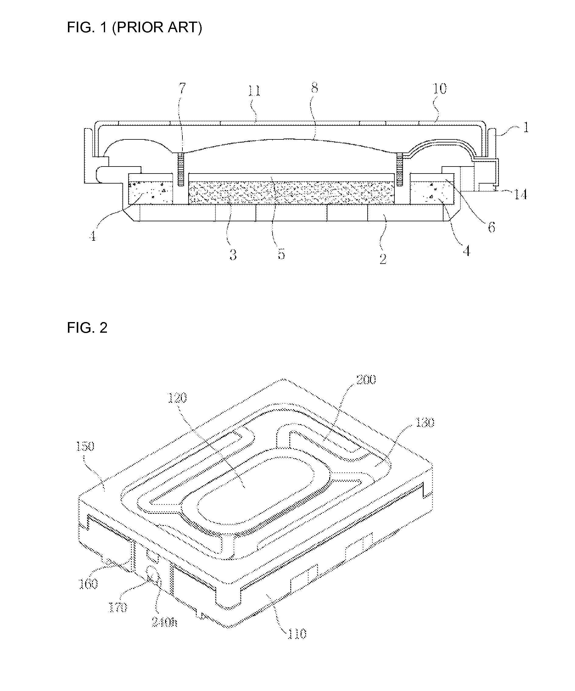
As a result, if the entire size of the sound converter does not increase, there is no sufficient vibration space for the upward dome-shaped diaphragm 8.
Once the vibration space is obtained, the magnetic circuit space decreases, which degrades characteristics.
This coil is often broken due to low strength, which results in low reliability.

Method used


Image

  • Acoustic transducer device
  • Acoustic transducer device
  • Acoustic transducer device

Examples


Embodiment Construction

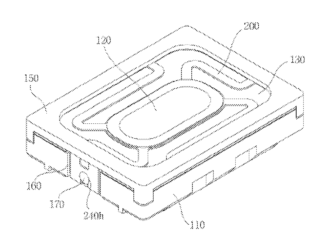
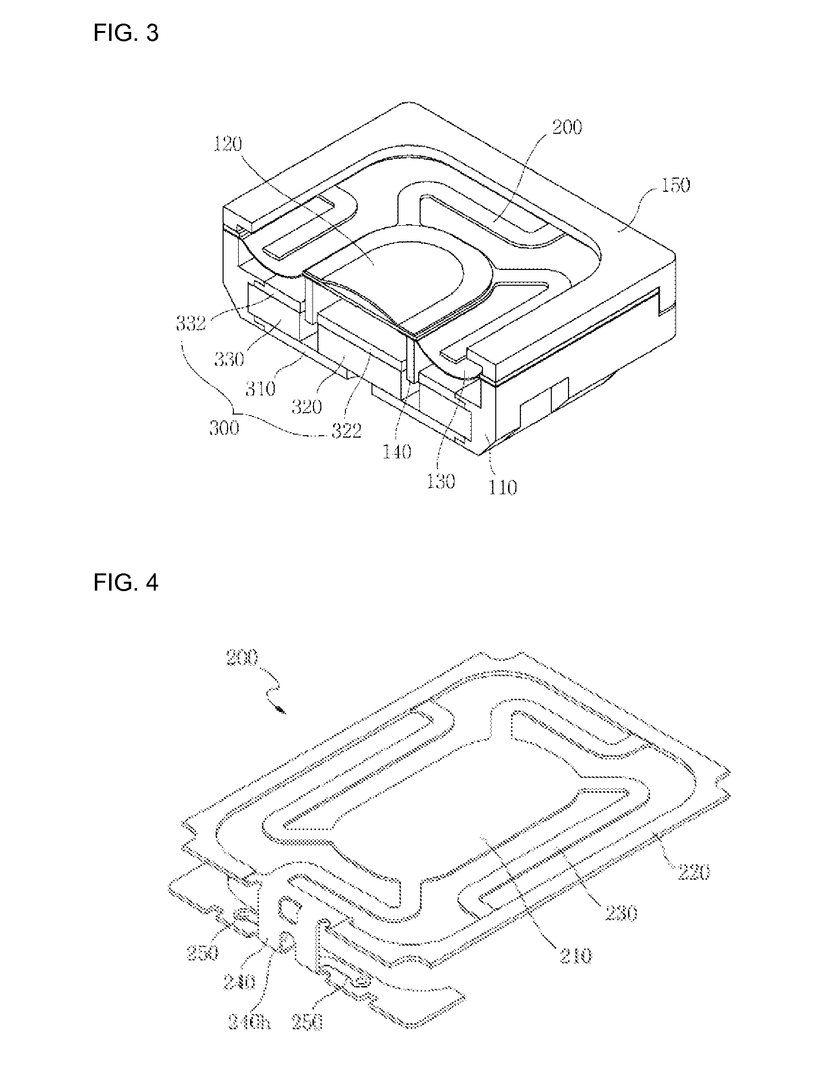
[0047]FIG. 2 is a perspective view of a sound converter according to a first embodiment of the present invention, and FIG. 3 is a cut-away perspective view of the sound converter according to the first embodiment of the present invention. In the sound converter according to the first embodiment of the present invention, a yoke assembly 300, in which an inner ring magnet 320 and an outer ring magnet 330 are attached to a yoke plate 310, is coupled to a frame 110, then a damper 200, a center diaphragm 120 and a side diaphragm 130 are provided so that a voice coil 140 attached to the damper 200 can be positioned in a gap between the inner ring magnet 320 and the outer ring magnet 330. An inner ring top plate 322 and an outer ring top plate 332 are respectively attached to the inner ring magnet 320 and the outer ring magnet 330. Next, a protector 150 is provided to protect the diaphragms 120 and 130. As can be seen in FIG. 3, a dome portion of the side diaphragm 130 projects to the bott...


PUM


Abstract

The present invention relates to a sound converter, and, more particularly, to a sound converter which can solve a problem in that a vibration space decreases in the sound converter requiring high outputs, as the overall height of a voice coil increases.

Description

TECHNICAL FIELD[0001]The present invention relates to a sound converter, and, more particularly, to a sound converter which can solve a problem in that a vibration space decreases in the sound converter requiring high outputs, as the overall height of a voice coil increases.BACKGROUND ART[0002]In general, a sound converter is used as a concept including a speaker, etc. The speaker converts electrical energy into mechanical energy through a voice coil present in a void according to Fleming's left hand rule to thereby generate sound.[0003]That is, when a current signal containing various frequencies is applied to the voice coil, the voice coil produces mechanical energy according to the intensity of the current and the magnitude of the frequency, causes vibration to a diaphragm attached to the voice coil, and ultimately generates a given magnitude of sound pressure which can be recognized by human ears.[0004]A magnetic circuit of the speaker is designed in a yoke made of a ferrous met...

Claims


Application Information

Patent Timeline
Patent Type & Authority Patents(United States)
IPC IPC(8): G10K13/00H04R1/00H04R7/00H04R9/06
CPCG10K13/00H04R7/04H04R7/16H04R9/041H04R9/06H04R9/02H04R9/04
Inventor KIMKO, KWAN HOKWON, JOONG HAK
Owner EM TECHNOLOGY CO LTD
Learn More