
Swimming pool skimmer plug and winterization system

a technology for swimming pools and winterization systems, which is applied in the field of swimming pool winterization or swimming pool sanitation systems, can solve the problems of wasting thousands of gallons of water in the process, and achieve the effects of reducing costs, saving customers even more money, and unusual gripping ability

Active Publication Date: 2014-08-05
HODAK JERRY
View PDF18 Cites 1 Cited by
  • Summary
  • Abstract
  • Description
  • Claims
  • Application Information

AI Technical Summary

Benefits of technology

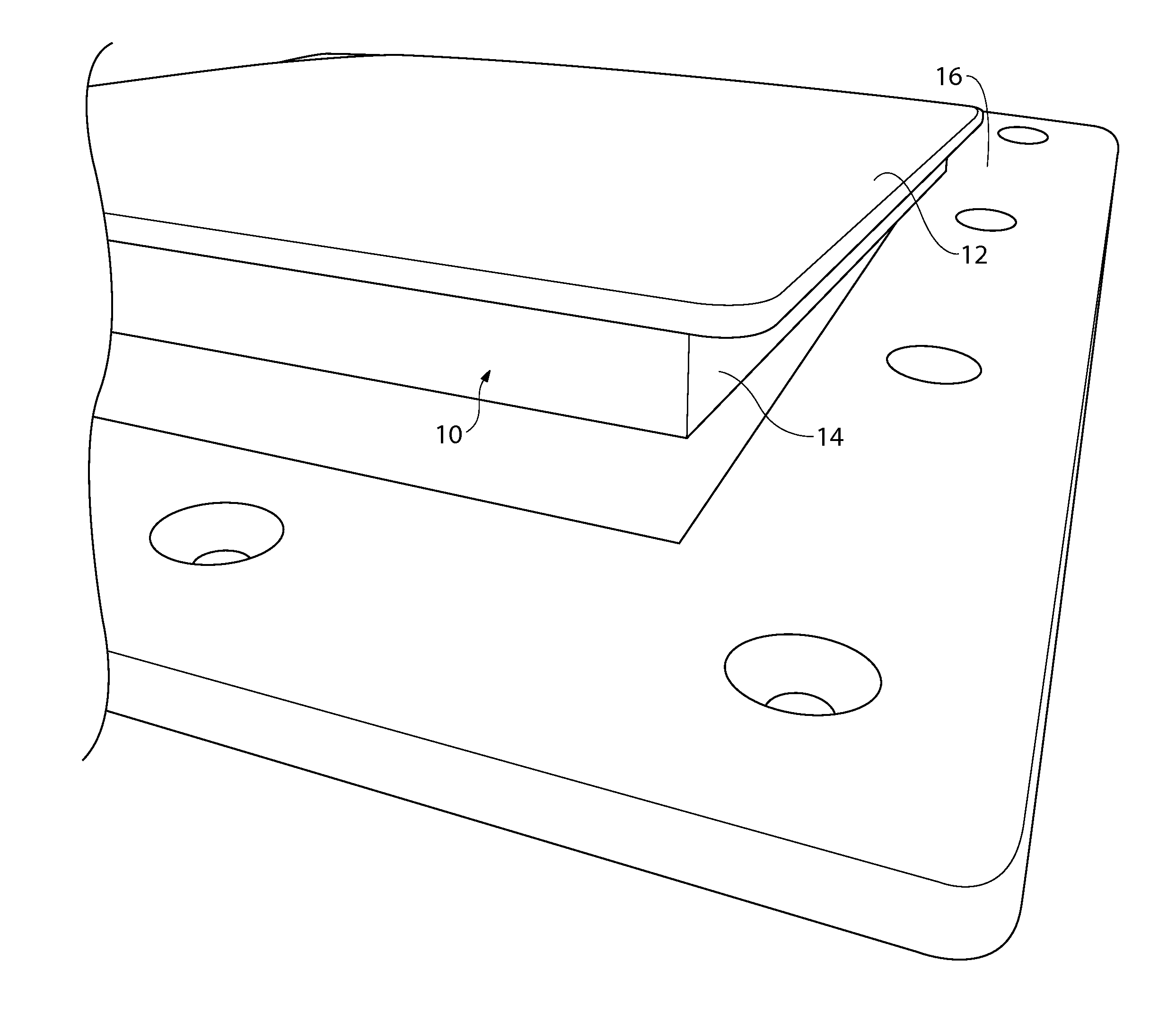
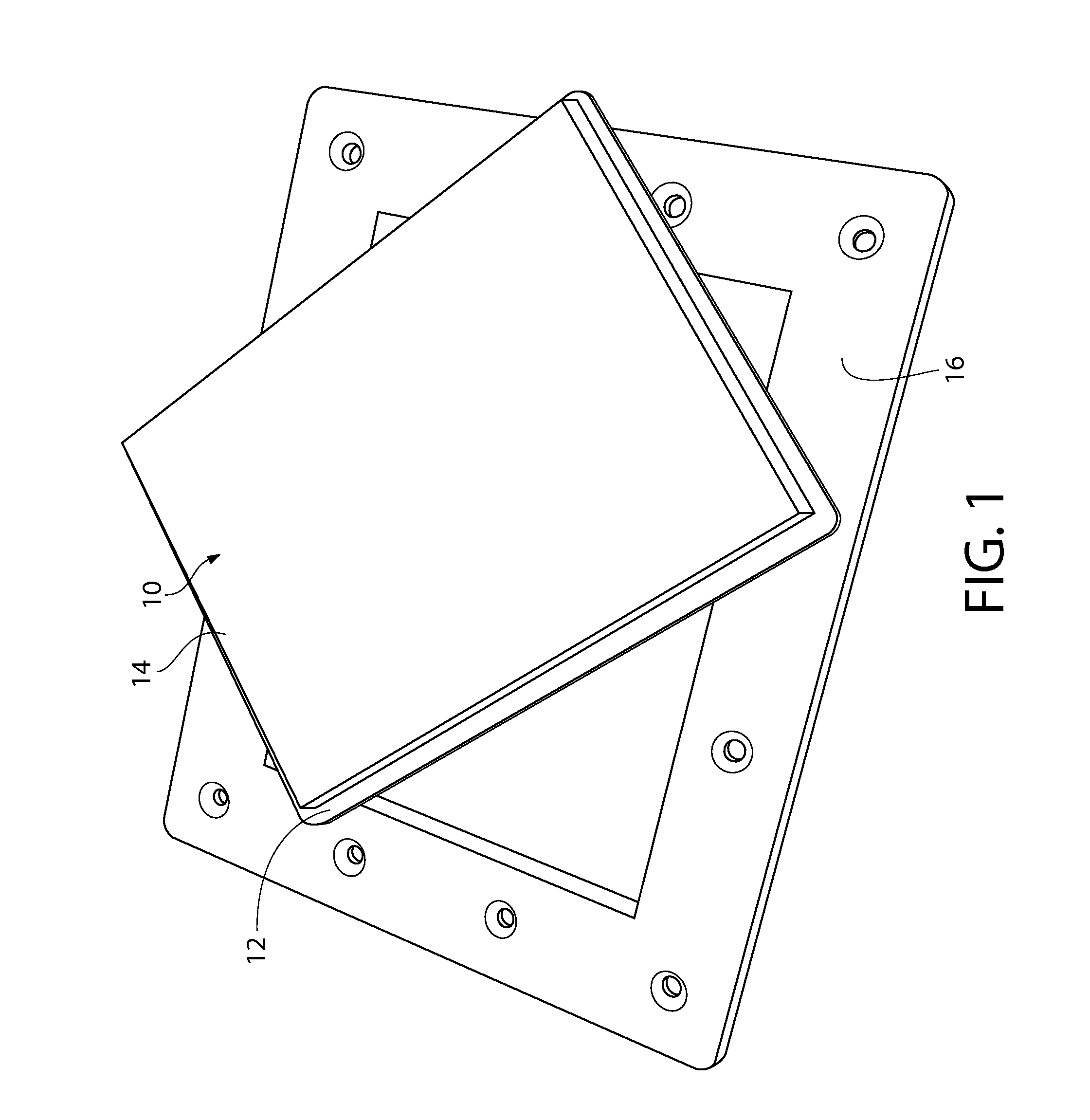
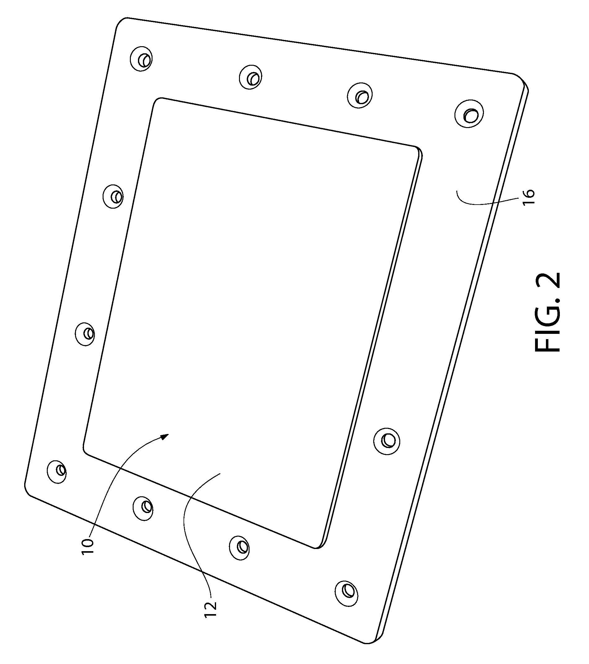
[0008]The skimmer plug is a ridged plastic plate made of HDPE, PVC, ABS or other similar type material that is rigid yet semi flexible and about ⅛ to ¼ inch in thickness or more, the plate generally measures slightly larger than that of the skimmer faceplate or skimmer opening so it does not push through and slip into the skimmer housing. The opposite side of this plate described above should be made from a cross linked (polyethylene) PE or neoprene rubber foam pad attached to the larger outer plate. Using a PSA (pressure sensitive adhesive) or waterproof glue, the foam pad will be bonded to the plate to make a single unit for use. This closed cell foam when inserted tightly into a skimmer opening has an unusual griping ability when wet. Once the foam makes it past the initial opening of the face plate or skimmer opening, it expands out over the inside edges with a popping noise and secures itself in place. This new design eliminates having to make a mating part for the lid to attach at substantially lower costs than other winter devices. After a few seasons of use, wore out foam pads could be sold separately as a replacement part for the skimmer plug saving the customer even more money.

Problems solved by technology

This procedure can waste thousands of gallons of water, as well as the related time in draining and refilling a large volume of water.

Method used


Image

  • Swimming pool skimmer plug and winterization system
  • Swimming pool skimmer plug and winterization system
  • Swimming pool skimmer plug and winterization system

Examples


Embodiment Construction

[0024]Prior to proceeding to the more detailed description of the present invention it should be noted that, for the sake of clarity and understanding, identical components which have identical functions have been identified with identical reference numerals throughout the several views illustrated in the drawing figures.

[0025]Reference is now made, to FIGS. 1 through 3. The current embodiment of the present invention comprises a skimmer plug, generally designated 10. Skimmer plug 10 comprises rigid plate 12 and closed cell foam 14. Skimmer plug 10 is designed to create a water tight seal with faceplate 16.

[0026]Reference is now made to FIG. 4 which shows a typical skimmer and water return set. Skimmer plug 10 can be modified to fit any skimmer / water return set. For the present set, a rectangular skimmer plug is capable of sealing skimmer opening 20 in skimmer plate 16 and a round skimmer plug is capable of sealing water return 22 in water return frame 18.

[0027]Reference is now made...


PUM


Abstract

The present invention is skimmer plug for winterizing a pool. The skimmer plug inserts and grips into the fluid opening, where there is fluid passage from the pool to the skimmer housing and filter assembly. In this manner, the surface of the skimmer plug when installed is slightly raised from the factory skimmer faceplate or skimmer opening by only the thickness of the skimmer plug's outer plate. The fasteners which secure the factory skimmer faceplate and the skimmer housing to the pool sidewall still remain accessible for adjustment by the pool owner or pool service personnel while the skimmer plug is securely in place.

Description

CROSS-REFERENCE TO RELATED APPLICATIONS[0001]This application is related to and claims priority from U.S. Provisional Patent Application Ser. No. 61 / 352,425 filed on Jun. 8, 2010.FIELD OF THE INVENTION[0002]This invention generally pertains to swimming pools and swimming pool sanitation. More specifically, the present invention relates to a system for winterizing or servicing a swimming pool.BACKGROUND OF THE INVENTION[0003]The invention is particularly applicable to swimming pools and will be described with particular reference thereto. However, it will be appreciated by those skilled in the art that the invention has broader applications and may also be adapted for use in other water or fluid control applications.[0004]Pools are traditionally drained below the opening of the skimmer intake in order to evacuate water from the skimmer housing and thus allowing for servicing or winterization of the pool. This procedure can waste thousands of gallons of water, as well as the related t...

Claims


Application Information

Patent Timeline
Patent Type & Authority Patents(United States)
IPC IPC(8): E04H4/00E04H4/12E04H4/14
CPCE04H4/14E04H4/1272
Inventor HODAK, JERRY
Owner HODAK JERRY
Learn More