Airbag device

a technology for airbags and joints, applied in the direction of pedestrian/occupant safety arrangements, vehicular safety arrangements, vehicle components, etc., can solve the problems of easy breakage of the joint portion, easy damage to the joint portion, so as to improve the workability of the airbag attachment and the effect of favorable breakage of the holding member

Active Publication Date: 2014-07-29
NIHON PLAST CO LTD
View PDF13 Cites 8 Cited by
  • Summary
  • Abstract
  • Description
  • Claims
  • Application Information

AI Technical Summary

Benefits of technology

[0013]In the above technique, the holding member is employed to cover the folded airbag to hold the folded state of the airbag. The slit-shaped breaking openings are provided to the holding member across the arrangement reference line in a zigzag manner, and are connected to each other by the narrow joint portions so as not to break in a normal situation. The folded airbag is covered with such a holding member. The above patent document states that, even when the arrangement reference line formed by folded lumps of the folded airbag is more or less shifted from a preset position, the airbag device can handle such a situation by having the breaking openings provided across the arrangement reference line.
[0015]The difference in the breaking timings of the multiple joint portions might be reduced by making the joint portions as narrow as possible. In this case, however, the very narrow joint portions are scattered at positions away from the center portion of the holding member. Then, it is hard for the joint portions to equally receive a pulling force generated for attachment of the holding member to the airbag, and the joint portion receiving a larger pulling force than the other joint portions might break easily during the attachment process.
[0017]The present invention aims to provide an airbag device having favorable performance in holding the shape of a folded airbag, favorable workability in attachment of the airbag to a holding member, and favorable breakability of the holding member upon deployment of the airbag.
[0022]According to the above configurations, the airbag device can have favorable performance in holding the shape of its folded airbag, favorable workability in attachment of the airbag to the holding member, and favorable breakability of the holding member upon deployment of the airbag.

Problems solved by technology

However, a bias in the deployment force applied to the joint portions is hard to correct.
When breaking timings of the multiple joint portions are different from each other, the deployment performance of the airbag is naturally affected by that.
Specifically, if one of the multiple joint portions breaks earlier than the others, the airbag can deploy from that joint portion relatively easily, but the other joint portions that break sequentially after the first one might affect the deployment of the airbag.
Then, it is hard for the joint portions to equally receive a pulling force generated for attachment of the holding member to the airbag, and the joint portion receiving a larger pulling force than the other joint portions might break easily during the attachment process.
Thus, not only the shape-holding performance, but also attachment workability is degraded drastically.

Method used


Image

  • Airbag device
  • Airbag device
  • Airbag device

Examples


Embodiment Construction

[0031]Embodiments of the invention of the present application are specifically described below with reference to the drawings.

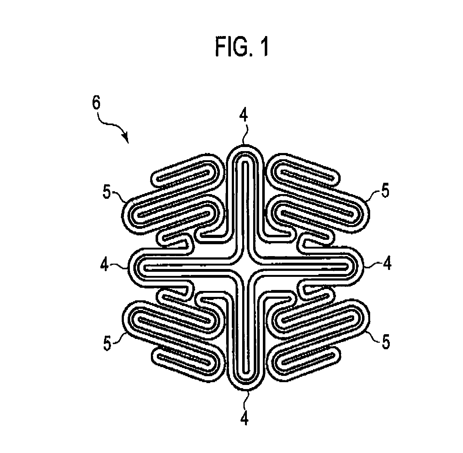
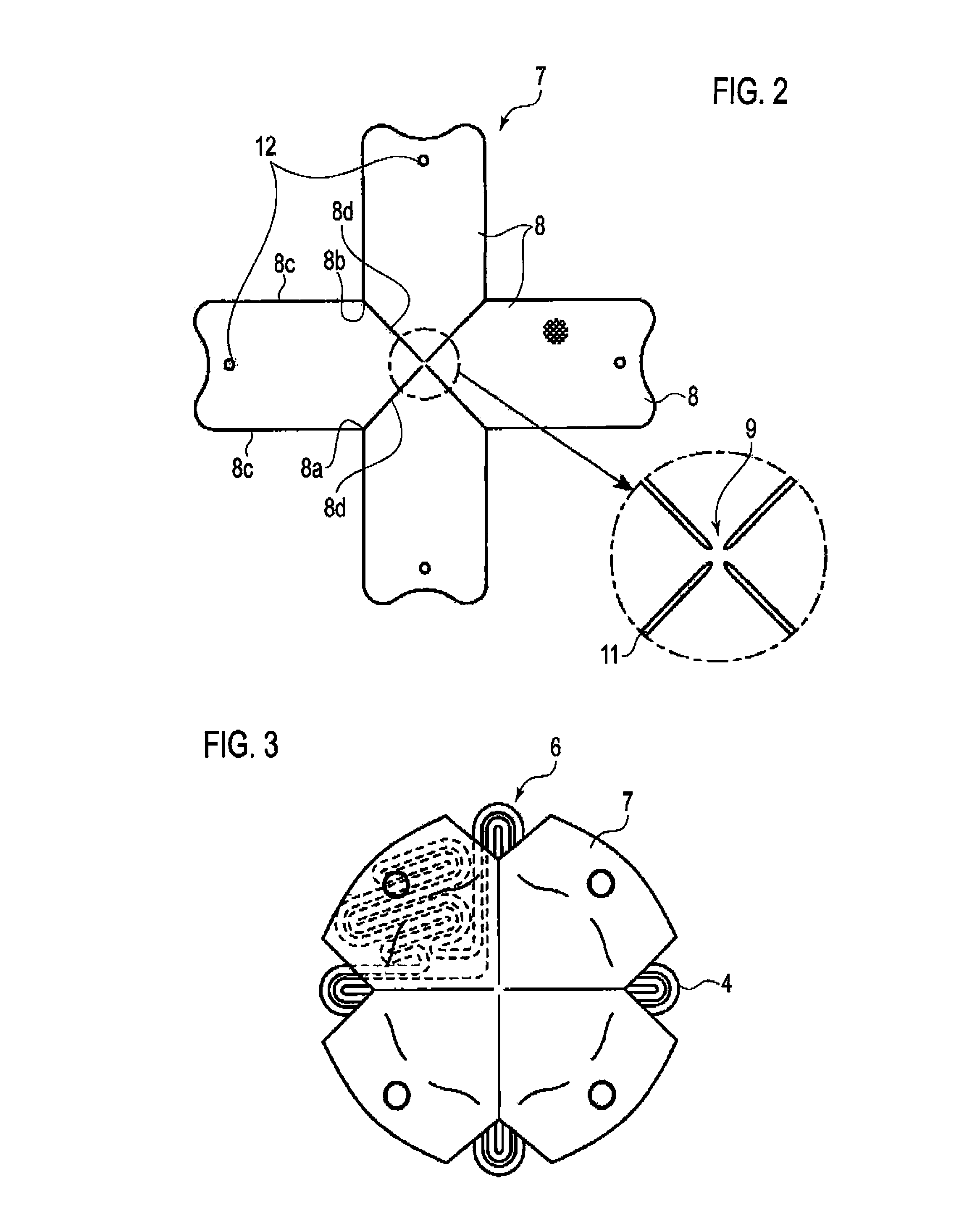
[0032]An airbag device according to a first embodiment of the present invention is described with reference to FIGS. 1 to 4E. There have conventionally been many means for folding an airbag housed in an airbag device. An airbag used in this embodiment is folded by an existing folding apparatus.

[0033]As shown in FIGS. 1 to 4E, the airbag device according to this embodiment is to be installed inside a center pad of a steering wheel as an airbag for the driver's seat. An airbag used in this airbag device is a bag body 1 having a pair of substantially-circular base cloths made of synthetic fiber called nylon 66, and the bag body 1 is formed by joining together periphery portions of the base cloths with jointing means such as sewing. Note that the airbag before being folded is called the bag body 1 whereas the airbag after being folded is called a folded airbag 6 ...


PUM


Abstract

An airbag device includes an airbag folded into a shape having a base portion, an upper surface opposite the base portion, and a side portion surrounding a portion between the base portion and the upper surface, and a holding member configured to cover the airbag as folded by being laid over the airbag as folded. The holding member has a plurality of cloth piece portions and a single connection portion connecting the plurality of cloth piece portions to one another. The connection portion of the holding member is located at the upper surface of the airbag as folded.

Description

CROSS REFERENCE TO RELATED APPLICATION[0001]This application is based upon and claims the benefit of priority from the prior Japanese Patent Application No. 2012-422192, filed on May 29, 2012, the entire contents of which are incorporated herein by reference.BACKGROUND[0002]1. Technical Field[0003]The present invention relates to an airbag device, and relates particularly to an airbag device having a holding member configured to maintain a folded shape of a folded airbag.[0004]2. Related Art[0005]Airbags are in widespread use as means for improving the safety of an occupant and the like in a travelling vehicle. An airbag is installed at a driver's seat, a front passenger's seat, a seatback, and / or a roof side rail of an automobile to buffer the impact received by the head, chest, waist, or knees of an occupant coming into contact with an interior component upon a frontal collision or a lateral collision. Moreover, in recent years, an airbag installed at a front cowl portion for prot...

Claims


Application Information

Patent Timeline
Patent Type & Authority Patents(United States)
IPC IPC(8): B60R21/16B60R21/20
CPCB60R21/237B60R21/201B60R21/203B60R2021/2178
Inventor TAKAGI, MAMORU
Owner NIHON PLAST CO LTD
Why Eureka
Try Eureka