
Pulse mode capability for operation of an RF/VHF impedance matching network with 4 quadrant, V.sub.RMS/I.sub.RMS responding detector circuitry

a technology of impedance matching and pulse mode, which is applied in the direction of process and machine control, measurement using ac-dc conversion, instruments, etc., can solve the problem that conventional rf matches cannot be actively tuned while, and achieve the effect of reducing reflected power

Active Publication Date: 2014-07-15
COMET TECH USA INC
View PDF0 Cites 18 Cited by
  • Summary
  • Abstract
  • Description
  • Claims
  • Application Information

AI Technical Summary

Benefits of technology

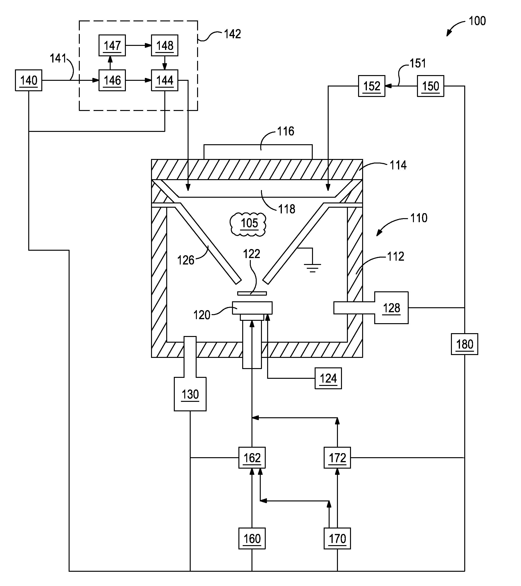
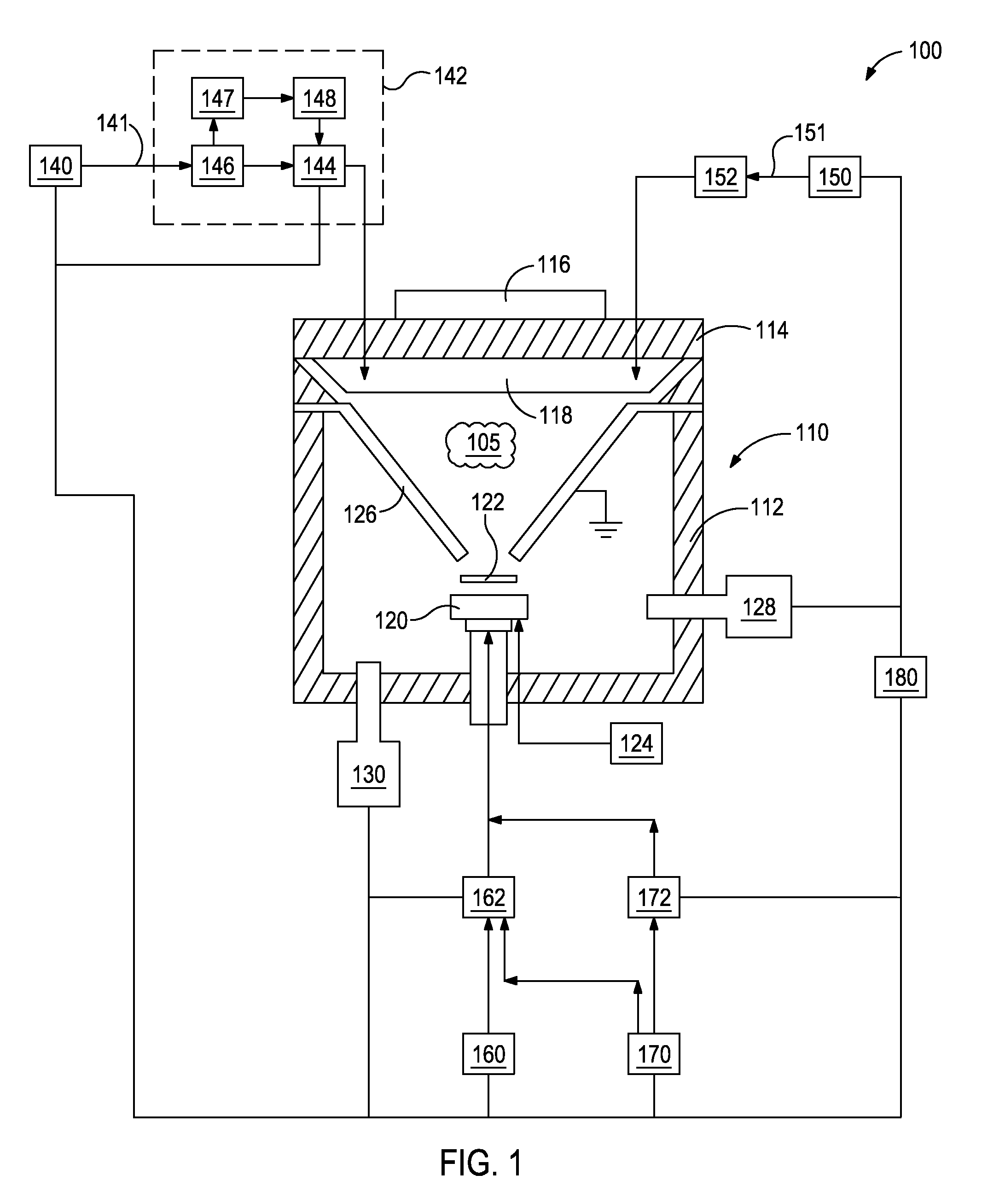
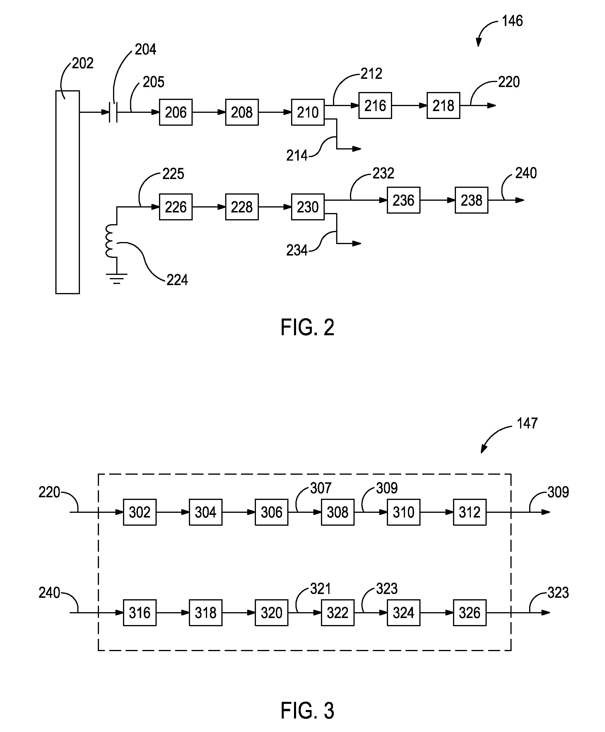
[0005]Embodiments of the disclosure may further provide a method for tuning an RF matching network for a plasma deposition chamber during pulse mode operation. The method may include transmitting a pulsing AC process signal from an RF generator to the plasma deposition chamber via the RF matching network. The method may also include sensing the pulsing AC process signal with a detector circuit coupled to the RF generator. The method may further include producing a pulsing AC voltage magnitude signal and a pulsing AC current magnitude signal with the detector circuit. The method may further include receiving and converting the pulsing AC voltage and current magnitude signals into a DC voltage envelope signal and a DC current envelope signal with an envelope circuit electrically coupled to the detector circuit. The method may further include varying an impedance of the RF matching network with a controller in response to the DC voltage and current envelope signals to reduce reflected power from the plasma deposition chamber, the controller being electrically coupled to the envelope circuit and the RF matching network.

Problems solved by technology

Conventional RF matches, however, cannot be actively tuned while the RF generator is in pulse mode.

Method used


Image

  • Pulse mode capability for operation of an RF/VHF impedance matching network with 4 quadrant, V.sub.RMS/I.sub.RMS responding detector circuitry
  • Pulse mode capability for operation of an RF/VHF impedance matching network with 4 quadrant, V.sub.RMS/I.sub.RMS responding detector circuitry
  • Pulse mode capability for operation of an RF/VHF impedance matching network with 4 quadrant, V.sub.RMS/I.sub.RMS responding detector circuitry

Examples


Embodiment Construction

[0012]It is to be understood that the following disclosure describes several exemplary embodiments for implementing different features, structures, or functions of the invention. Exemplary embodiments of components, arrangements, and configurations are described below to simplify the present disclosure, however, these exemplary embodiments are provided merely as examples and are not intended to limit the scope of the invention. Additionally, the present disclosure may repeat reference numerals and / or letters in the various exemplary embodiments and across the Figures provided herein. This repetition is for the purpose of simplicity and clarity and does not in itself dictate a relationship between the various exemplary embodiments and / or configurations discussed in the various Figures. Moreover, the formation of a first feature over or on a second feature in the description that follows may include embodiments in which the first and second features are formed in direct contact, and m...


PUM

PropertyMeasurementUnit
pressureaaaaaaaaaa
impedanceaaaaaaaaaa
frequenciesaaaaaaaaaa

Abstract

A physical vapor deposition system may include an RF generator configured to supply a pulsing AC process signal to a target in a physical vapor deposition chamber via the RF matching network. A detector circuit may be coupled to the RF generator and configured to sense the pulsing AC process signal and to produce a corresponding pulsing AC voltage magnitude signal and pulsing AC current magnitude signal. An envelope circuit may be electrically coupled to the detector circuit and configured to receive the pulsing AC voltage and current magnitude signals and to produce a DC voltage envelope signal and a DC current envelope signal. A controller may be electrically coupled to the envelope circuit and the RF matching network and configured to receive the DC voltage and current envelope signals and to vary an impedance of the RF matching network in response to the DC voltage and current envelope signals.

Description

BACKGROUND[0001]Physical vapor deposition (“PVD”) systems are used to deposit thin layers of a target material onto a substrate. PVD systems generally include a radio frequency (“RF”) generator that transmits a continuous and / or pulsing signal to a deposition chamber. An RF match having a variable impedance is generally located between the RF generator and the chamber. The RF match may be tuned, i.e., the impedance may be varied, to make the impedance of the RF match be the complex conjugate of the deposition chamber's impedance. Tuning the RF match reduces reflected power from the chamber, thereby increasing the power transferred from the RF generator to the deposition chamber and into the plasma deposition process.[0002]Oftentimes the RF generator is run in pulse mode and transmits a pulsing AC signal to the deposition chamber rather than a continuous AC signal. Conventional RF matches, however, cannot be actively tuned while the RF generator is in pulse mode. Instead, the convent...

Claims


Application Information

Patent Timeline
Patent Type & Authority Patents(United States)
IPC IPC(8): G05F3/00
CPCH01J37/32183H03H7/40
Inventor BOSTON, GERALD, E.
Owner COMET TECH USA INC
Learn More