
Organic electroluminescence device and material for organic electroluminescence device

a technology of electroluminescence device and organic electroluminescence, which is applied in the direction of discharge tube/lamp details, luminescence screen of discharge tube, natural mineral layered products, etc., can solve the problems of insufficient practical application of improved luminous efficiency and lifetime, short life of organic electroluminescence device, and considerable degradation of molecules, etc., to achieve long lifetime, high efficiency, and high efficiency

Active Publication Date: 2014-07-15
IDEMITSU KOSAN CO LTD
View PDF40 Cites 31 Cited by
  • Summary
  • Abstract
  • Description
  • Claims
  • Application Information

AI Technical Summary

Benefits of technology

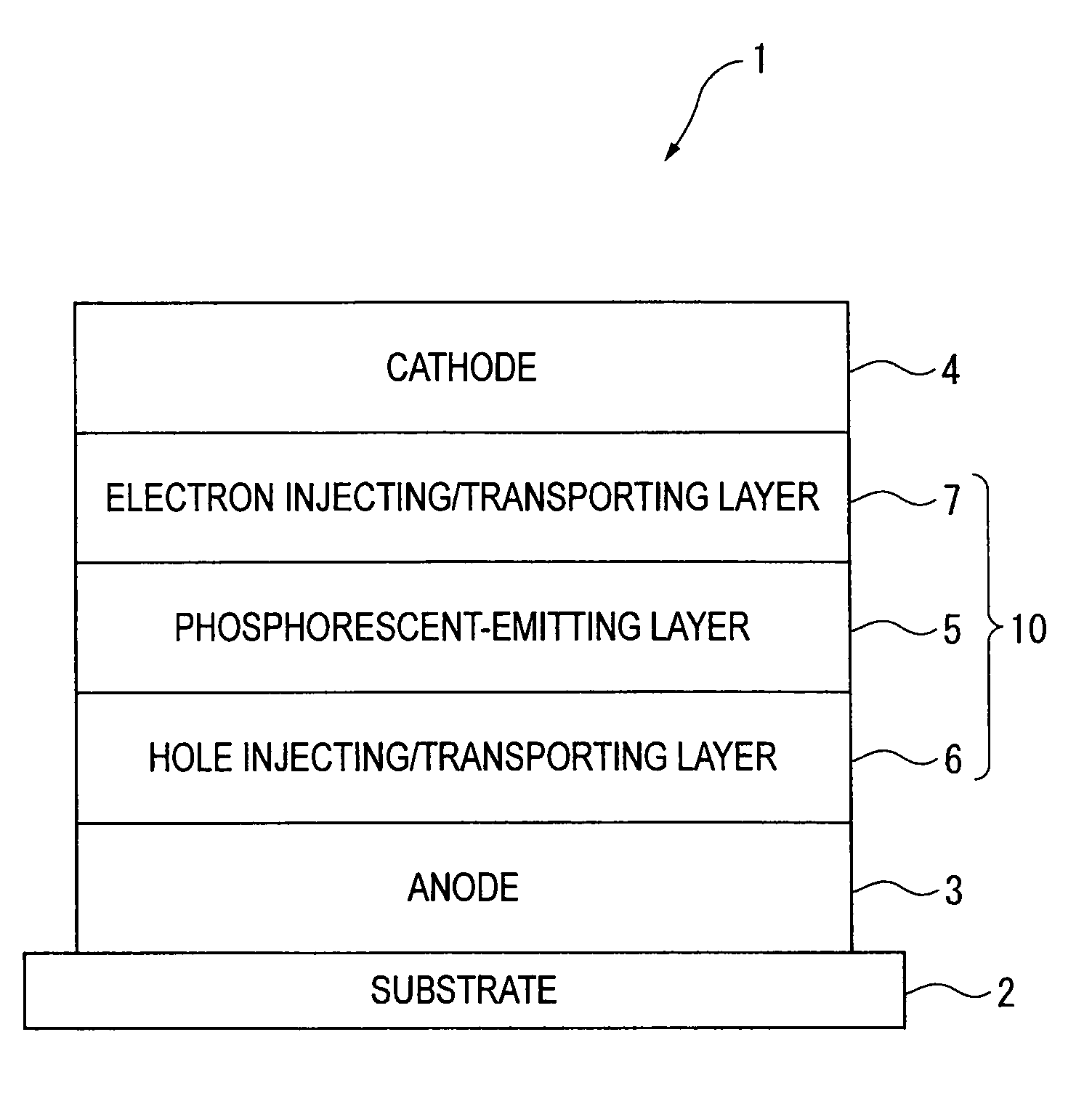
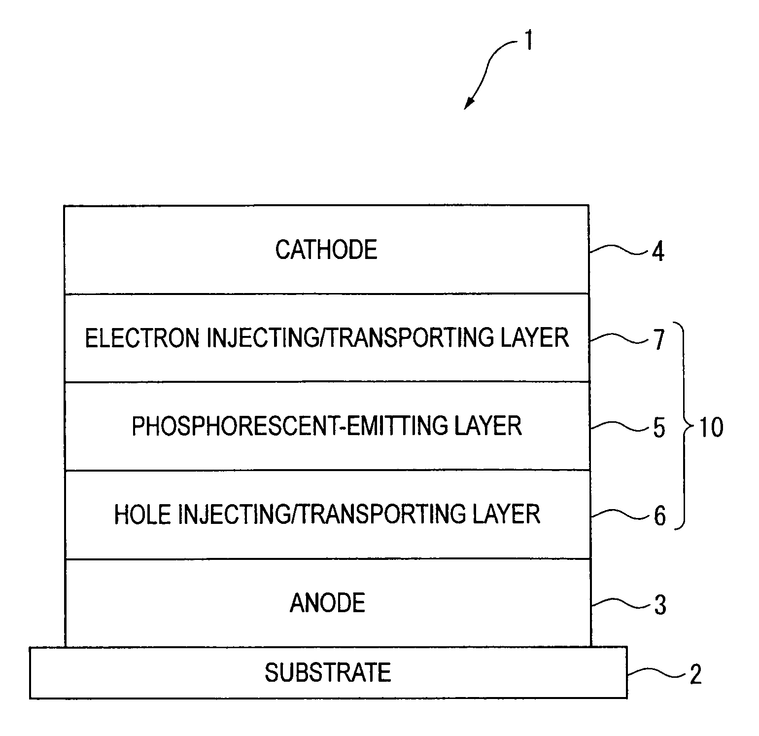
[0029]An object of the present invention is to provide a phosphorescent organic EL device having high efficiency and long lifetime and a material for an organic EL device from which a phosphorescent organic EL device having high efficiency and long lifetime can be formed.
[0030]After conducting concentrated studies in order to achieve such an object, the inventors have found that a phosphorescent organic EL device having high efficiency and long lifetime can be provided by using a material containing a host material represented by the following formula (1) or a host material represented by the following formula (3) or (4) as a phosphorescent host, and reached the present invention.

Problems solved by technology

However, although an organic EL device in which CBP is used as the host material exhibits much higher luminous efficiency due to phosphorescent emission, the organic EL device has such a short lifetime as to be practically inapplicable.
Such a problem is considered to be attributed to considerable degradation of molecules by holes due to not-high oxidation stability that the molecular structure of CBP exhibits.
Although the technique disclosed in the patent document 2 contributes to an improvement in the luminous efficiency and lifetime, the improved luminous efficiency and lifetime are not always sufficient for practical application.
Accordingly, it is not successful to simply apply the fluorescent host to the host material (phosphorescent material) for a phosphorescent-emitting layer.
Thus, energy cannot be reliably transferred to a phosphorescent dopant for emitting light having a wavelength in a visible light range of 500 nm to 720 nm.
Accordingly, an anthracene derivative is not suitable for the phosphorescent host.
Further, derivatives such as a perylene derivative, a pyrene derivative and a naphthacene derivative are not preferable phosphorescent hosts for the same reason above.
However, none of the above documents refers to effectiveness of aromatic hydrocarbon compounds as the phosphorescent hosts.
As described above, no host material has been known to be capable of efficiently transferring energy to the phosphorescent material while exhibiting such a long lifetime as to be practically applicable, which has hindered a practical realization of a device in which a phosphorescent material is used.

Method used


Image

  • Organic electroluminescence device and material for organic electroluminescence device
  • Organic electroluminescence device and material for organic electroluminescence device
  • Organic electroluminescence device and material for organic electroluminescence device

Examples


synthesis example

[0312]Compounds according to the present invention can be synthesized by Suzuki-Miyaura cross coupling reaction.

[0313]Next, a manufacturing method of the host material according to the present invention will be described with reference to synthesis example(s). However, the present invention is not limited to the description made herein.

[0314]

synthesis example 1

Synthesis of Compound A1

Synthesis of 2-bromo-6-(2-naphthyl)naphthalene

[0315]Under an argon gas atmosphere, 246 g (860 mmol) of 2,6-dibromonaphthalene, 163 g (950 mmol) of 2-naphthalene boronic acid, 20 g (17.0 mmol) of tetrakis(triphenylphosphine)palladium(0), 3 L of dimethoxyethane (DME) and 1.5 L of 2M sodium carbonate solution were mixed, and stirred for 16 hours while being refluxed. After the completion of the reaction, precipitated crystal was separated by filtration. Then, the obtained solid was cleansed with water, methanol and hexane. The obtained solid was dried under reduced pressure, and 197 g of 2-bromo-6-(2-naphthyl)naphthalene was obtained at an yield of 69%.

[0316]Under an argon gas atmosphere, 5.00 g (15.0 mmol) of 2-bromo-6-(2-naphthyl)naphthalene, 3.50 g (15.8 mmol) of 9-phenanthreneboronic acid, 0.87 g (0.750 mmol) of tetrakis(triphenylphosphine)palladium(0), 50 mL of toluene, 50 mL of dimethoxyethane and 22.5 mL of 2M sodium carbonate solution were mixed, and sti...

synthesis example 2

Synthesis of Compound A6

[0318]Under an argon gas atmosphere, 5.00 g (13.0 mmol) of 6,12-dibromochrysene, 6.04 g (27.2 mmol) of 9-phenanthreneboronic acid, 0.75 g (0.65 mmol) of tetrakis(triphenylphosphine)palladium(0), 50 mL of toluene, 50 mL of dimethoxyethane and 40 mL of 2M sodium carbonate solution were mixed, and stirred for 10 hours at 90 degrees C. Subsequently, the reaction mixture was warmed up to room temperature, added with water and stirred for 1 hour. After the solid precipitated during the reaction was separated by filtration, the obtained solid was cleansed with water, methanol, dimethoxyethane and toluene in this order. By dissolving the obtained solid in toluene and refining the solution by silica-gel column chromatography, 4.6 g of the compound A6 was obtained at an yield of 61%.

[0319]Mass-spectrum analysis consequently showed that m / e was equal to 580 while a calculated molecular weight was 580.22.

[0320]


PUM


Abstract

An organic electroluminescence device includes: a cathode; an anode; and a single-layered or multilayered organic thin-film layer provided between the cathode and the anode. The organic thin-film layer includes at least one emitting layer. The at least one emitting layer contains at least one phosphorescent material and a host material represented by the following formula (1).Ra—Ar1—Rb  (1)In the formula, Ar1, Ra and Rb each represent a substituted or unsubstituted benzene ring or a condensed aromatic hydrocarbon ring selected from a substituted or unsubstituted naphthalene ring, a substituted or unsubstituted chrysene ring, a substituted or unsubstituted fluoranthene ring, a substituted or unsubstituted phenanthrene ring, a substituted or unsubstituted benzophenanthrene ring, a substituted or unsubstituted dibenzophenanthrene ring, a substituted or unsubstituted triphenylene ring, a substituted or unsubstituted benzo[a]triphenylene ring, a substituted or unsubstituted benzochrysene ring, a substituted or unsubstituted benzo[b]fluoranthene ring and a substituted or unsubstituted picene ring. Substituents for Ra and Rb are not aryl groups.

Description

CROSS-REFERENCE TO RELATED APPLICATIONS[0001]This application is a continuation-in-part of U.S. Ser. No. 12 / 108,066 filed Apr. 23, 2008 and claims the benefit of U.S. 61 / 053,908 filed May 16, 2008, JP 2007-179109 filed Jul. 7, 2007, JP 2007-179120 filed Jul. 7, 2007, and JP 2007-179121 filed Jul. 7, 2007.BACKGROUND OF THE INVENTION[0002]1. Field of the Invention[0003]The present invention relates to an organic electroluminescence device (hereinafter abbreviated as organic EL device) and a material for an organic electroluminescence device. In particular, the present invention relates to an organic electroluminescence device including a red emitting layer and a material used for the organic electroluminescence device.[0004]2. Description of Related Art[0005]An organic EL device, which includes an organic thin-film layer (in which an emitting layer is included) between an anode and a cathode, has been known to emit light using exciton energy generated by a recombination of holes and e...

Claims


Application Information

Patent Timeline
Patent Type & Authority Patents(United States)
IPC IPC(8): H01L51/54H05B33/14C09K11/06
CPCC09K11/06C09K2211/1011H05B33/14H05B33/20H10K85/615H10K85/626H10K85/657H10K85/6572H10K85/346H10K85/342H10K50/11H10K2101/10H10K50/14H10K50/171H10K2102/103
Inventor NISHIMURA, KAZUKIIWAKUMA, TOSHIHIROFUKUOKA, KENICHIHOSOKAWA, CHISHIOKAWAMURA, MASAHIROITO, MITSUNORITAKASHIMA, YORIYUKIOGIWARA, TOSHINARI
Owner IDEMITSU KOSAN CO LTD
Learn More