Wiper apparatus for vehicle

a technology for wipers and vehicles, applied in vehicle cleaning, curtain suspension devices, roofs, etc., can solve the problems of affecting the working efficiency of workers, so as to improve the structure and improve the effect of vibration control

Active Publication Date: 2014-07-08
DYAUTO
View PDF16 Cites 2 Cited by
  • Summary
  • Abstract
  • Description
  • Claims
  • Application Information

AI Technical Summary

Benefits of technology

[0007]The present invention provides a wiper apparatus for a vehicle having improved vibration control and allowing a worker to check the assembly state with the naked eye by improving a structure of the wiper apparatus to be assembled onto an auto body panel in a rotational manner without the need for bolts or screws.

Problems solved by technology

Such assembling of the wiper apparatus onto the auto body panel with bolts and nuts arises an issue of dropping working efficiency.
Furthermore, conventional assembling requires welding weld nuts onto the auto body panel, thus arising another issue of cost-ineffective manufacturing.
With the wiper apparatus, however, a worker has difficulty checking with the naked eye whether the wiper apparatus is completely assembled onto the auto body panel.
In addition, a vibration control between the auto body panel and the wiper apparatus is so weak that the vibration occurring when the wiper apparatus is working may propagate to the auto body panel.

Method used


Image

  • Wiper apparatus for vehicle
  • Wiper apparatus for vehicle
  • Wiper apparatus for vehicle

Examples


Embodiment Construction

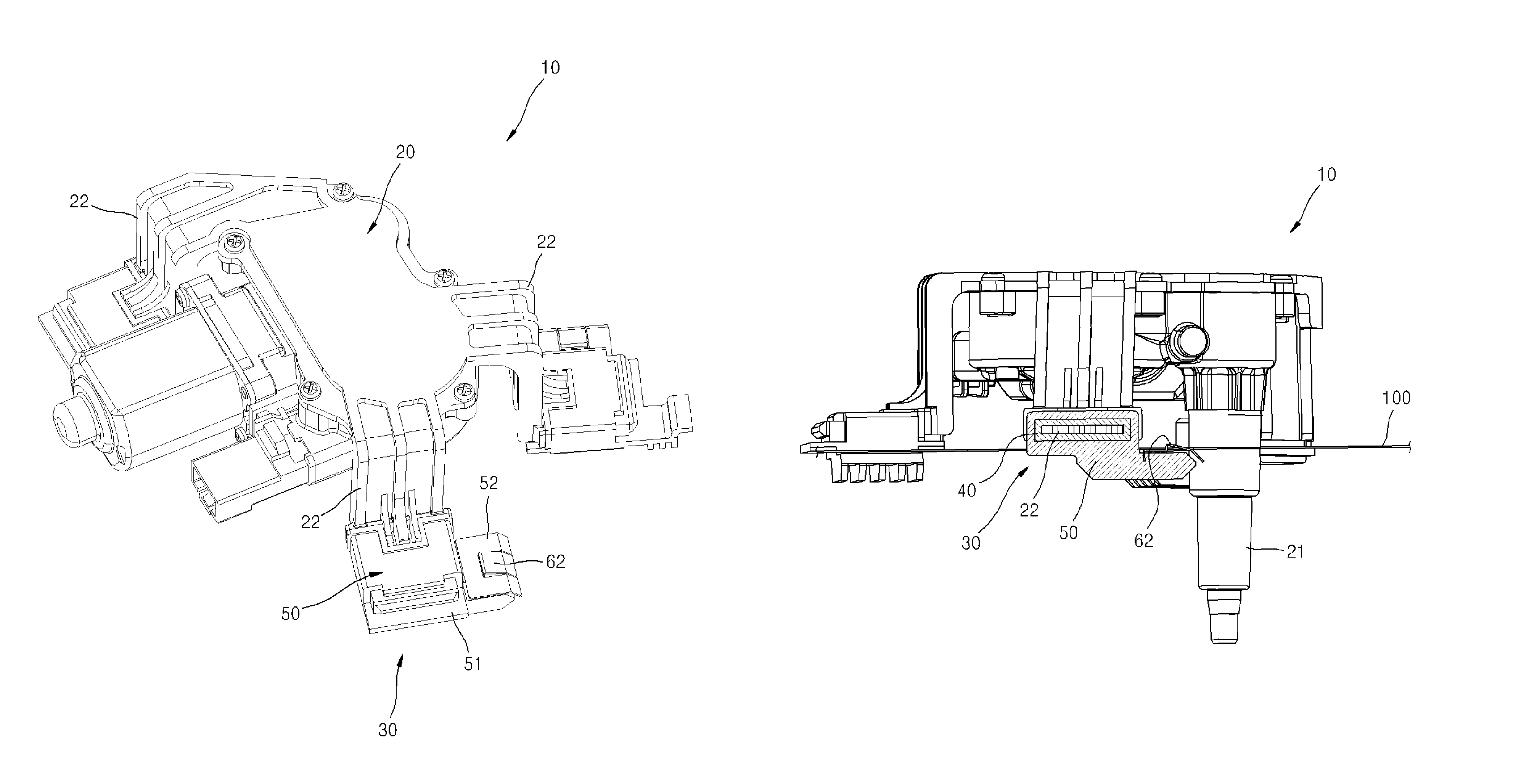
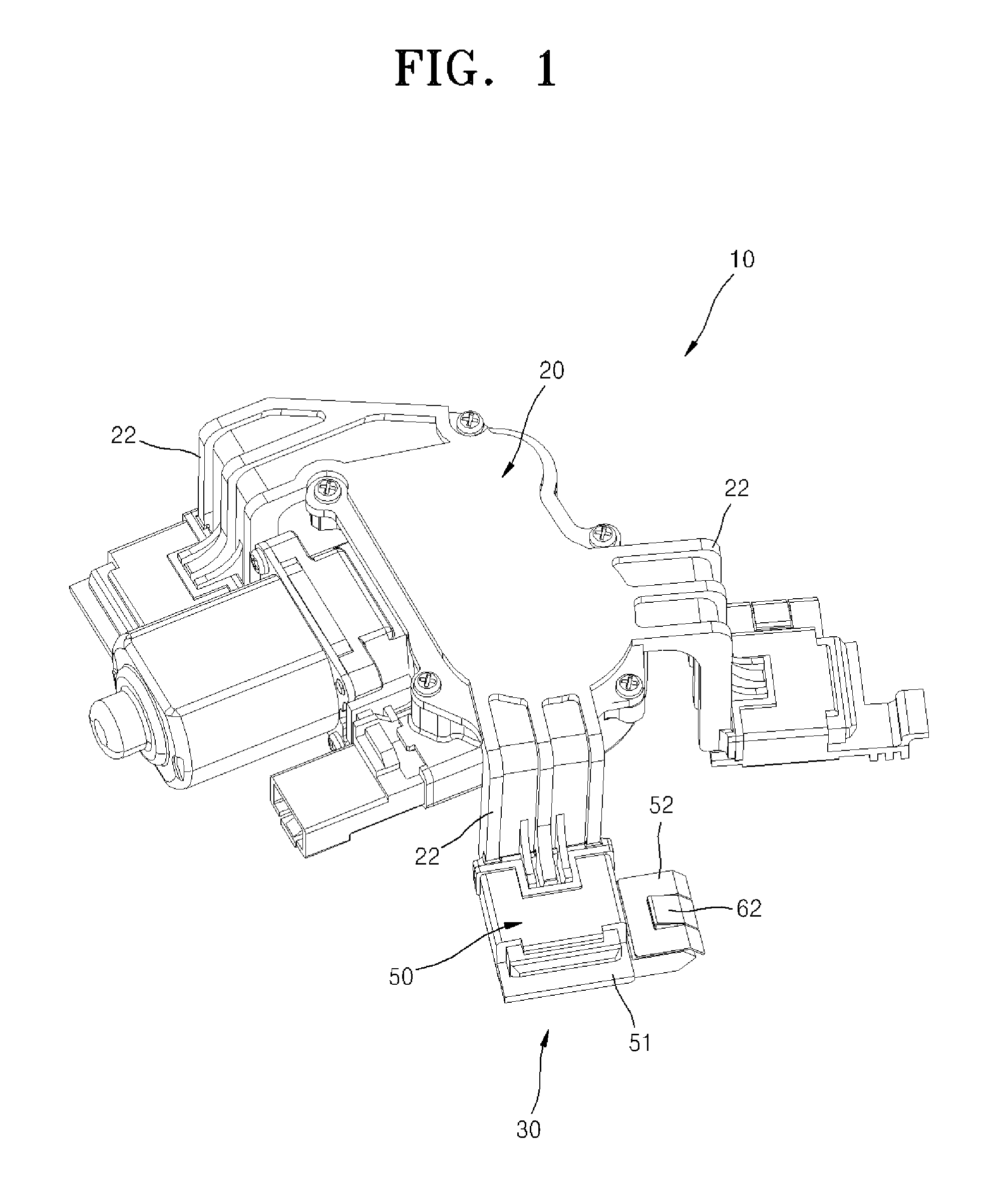
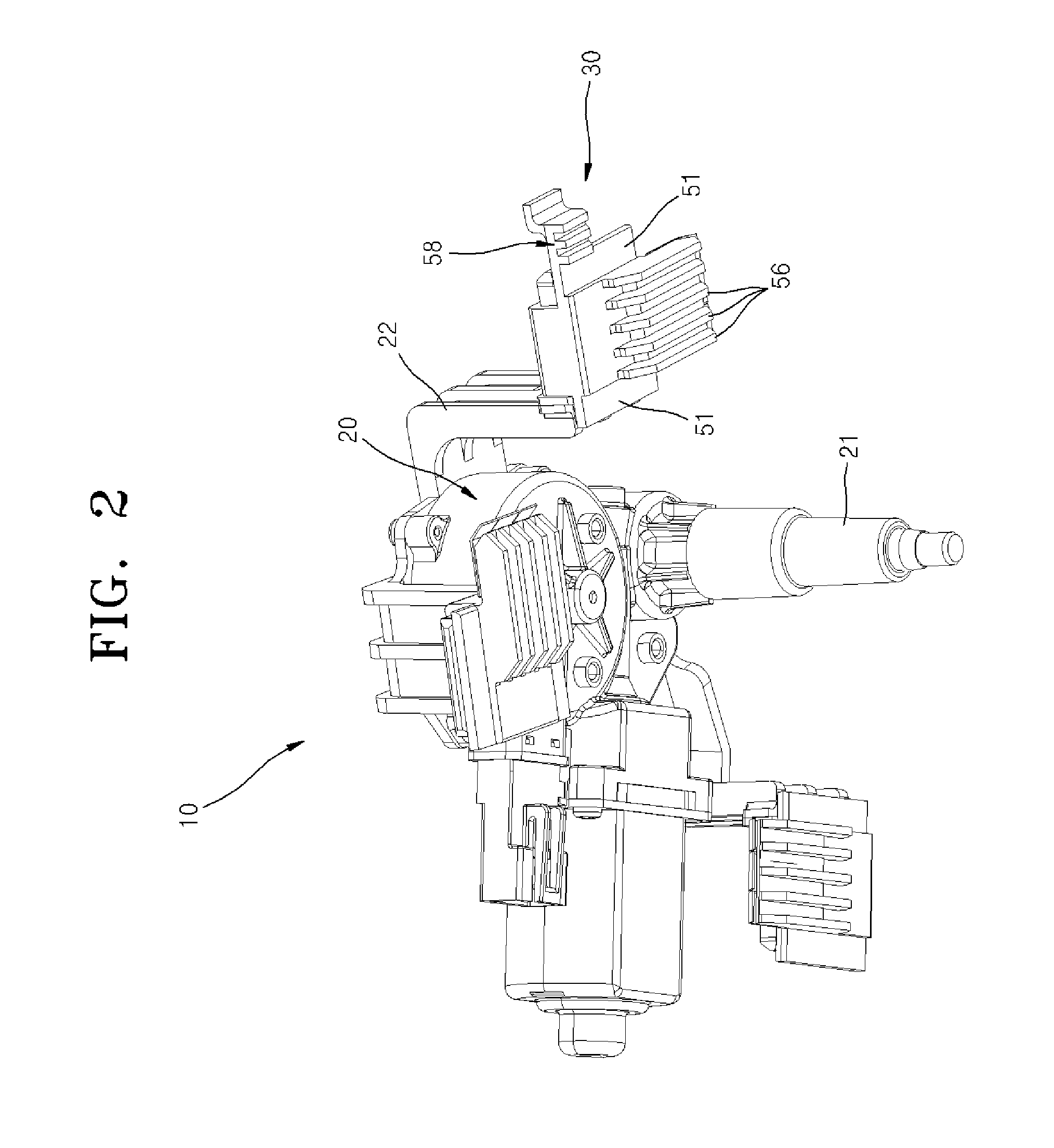
[0023]FIG. 1 is a perspective view of a wiper apparatus 10 for a vehicle, according to an embodiment of the present invention. FIG. 2 is a diagram of the wiper apparatus 10 of FIG. 1, viewed from a different direction. FIG. 3 is a plane view of the wiper apparatus 10 of FIG. 1. FIG. 4 is a cross-sectional view along line IV-IV shown in FIG. 3. FIG. 5 is a cross-sectional view along line V-V shown in FIG. 3. FIG. 6 is a diagram of the wiper apparatus 10 with a jointing member 30 separated therefrom. FIG. 7 is a split perspective view of main elements of the jointing member 30 of FIG. 6. FIGS. 8 and 9 show a procedure of assembling the wiper apparatus 10 of FIG. 1 onto an auto body panel 100.

[0024]Referring to FIGS. 1 to 9, the wiper apparatus 10 is an apparatus for cleaning e.g. a windshield or rear window of a vehicle. The wiper apparatus 10 includes a frame 20, a supporter 22, and the jointing member 30.

[0025]The frame 20 receives a wiper driving motor. An output axis 21 of the wip...


PUM


Abstract

A wiper apparatus for a vehicle, including: a frame to receive a wiper driving motor; a supporter formed to protrude from the frame toward an auto body panel; and a jointing member that combines with the supporter and that joins to the auto body panel, wherein the jointing member forms an ‘L’ shape in a longitudinal cross-section including a direction in which the jointing member is finally assembled into the auto body panel, and includes a first pressing part for contacting and supporting one side of the auto body panel; a second pressing part for contacting and supporting the other side of the auto body panel; and a protruding stopper for preventing the auto body panel from rotating in a direction parallel to the auto body panel.

Description

CROSS-REFERENCE TO RELATED APPLICATIONS[0001]The present application claims priority of Korean patent application No. 10-2012-0041602 filed on Apr. 20, 2012, the content of which is incorporated herein by reference.FIELD OF THE INVENTION[0002]The present invention relates to a wiper apparatus for a vehicle, and more particularly, to a technology to be applied to a windshield wiper apparatus for a vehicle.BACKGROUND OF THE INVENTION[0003]Generally, a wiper apparatus for a vehicle is a kind of safety device for securing a driver's view by wiping off rain, snow, dust, or stains from the windshield with wiper blades. The wiper apparatus may be mounted not only on the windshield but also on a rear window, an outside rear view mirror, a head lamp, etc. Especially, the wiper apparatus mounted on the windshield typically includes a pair of wiper blades connected to a motor via a linkage tool to operate them. An example of the wiper apparatus is disclosed in the published Korean Patent No. 2...

Claims


Application Information

Patent Timeline
Patent Type & Authority Patents(United States)
IPC IPC(8): B60S1/04
CPCB60S1/0438B60S1/0447B60S1/04B60S1/08
Inventor KO, KYOUNG, HO
Owner DYAUTO
Why Eureka
Try Eureka