Eureka AIR delivers breakthrough ideas for toughest innovation challenges, trusted by R&D personnel around the world.

Power converter bus control method, system, and article of manufacture

a power converter and bus technology, applied in the direction of dc-ac conversion without reversal, dc circuit to reduce harmonics/ripples, instruments, etc., can solve the problems of high reactive power reciprocation, inability to provide reactive power for other loads, and additional power drawn and subsequently released , to achieve the effect of improving the power output efficiency of the inverter

Active Publication Date: 2014-07-01
ENPHASE ENERGY
View PDF12 Cites 36 Cited by
  • Summary
  • Abstract
  • Description
  • Claims
  • Application Information

AI Technical Summary

Benefits of technology

The patent text describes methods for controlling and managing the power conversion process in systems that provide power to a grid network. The technology allows for the selective control of power conversion, which can include setting the voltage and phase angles of an inverter to optimize the power factor and waveform levels. The technology also uses real-time calculations and curved matching techniques to maintain optimal performance. By combining the management of bus voltage and phase shift, the technology can maximize power output efficiency of the inverter. Overall, the technology aims to improve the performance and efficiency of power systems.

Problems solved by technology

Reactive power is not available for other loads when it is reciprocating in the circuit.
As a result high reactive power reciprocation is not favored.
The characteristics of a non-linear load may also act to distort the waveform of an AC power form, thereby distorting the signal and resulting in additional power being drawn and subsequently released.
Other circuit properties may impose reactive power inefficiencies as well.
This increased reactive power is disfavored as the reactive power is unavailable for other uses when it is reciprocating in the circuit.
Also, the reciprocating reactive power can contribute to current losses from heat or other imperfections in the circuit.

Method used


Image

  • Power converter bus control method, system, and article of manufacture
  • Power converter bus control method, system, and article of manufacture
  • Power converter bus control method, system, and article of manufacture

Examples


Embodiment Construction

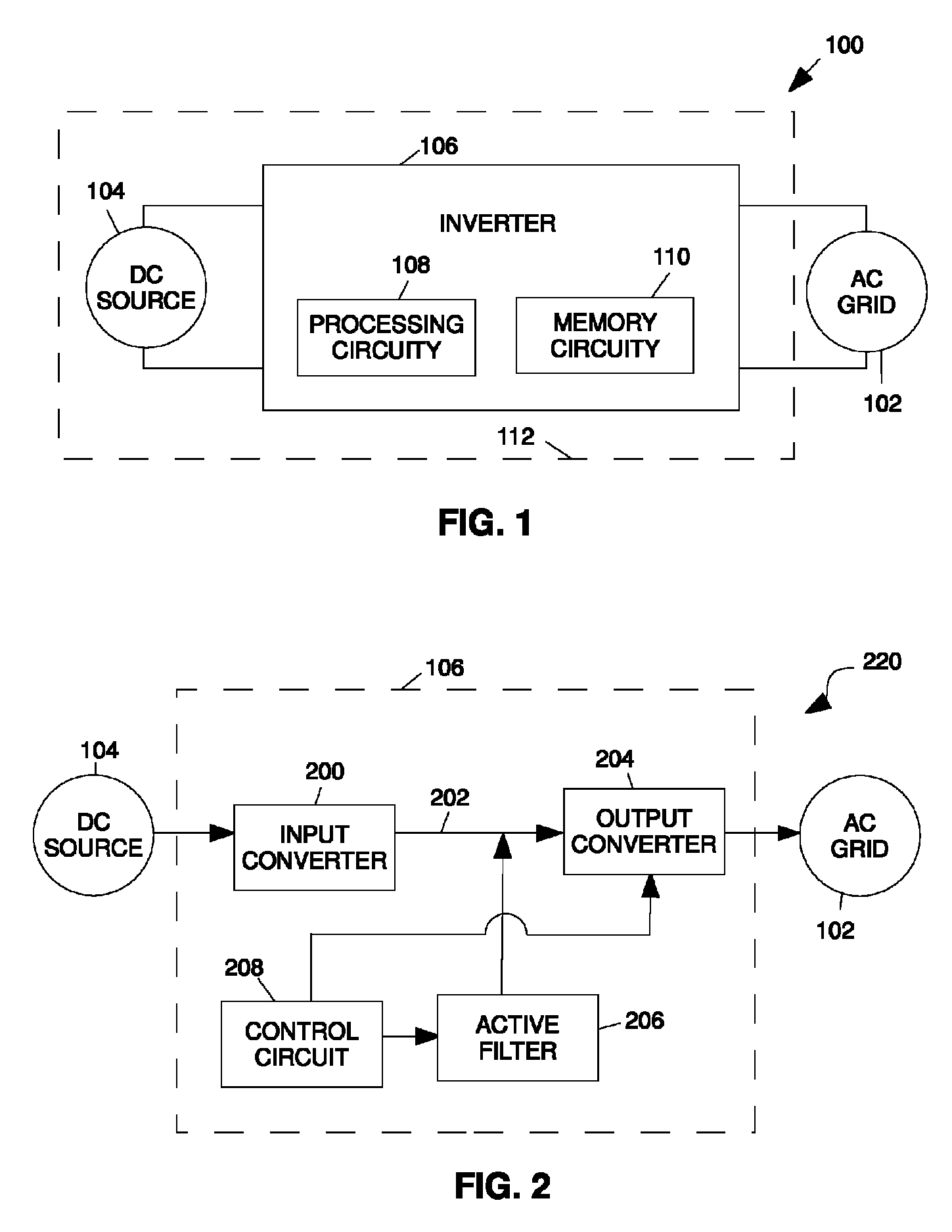
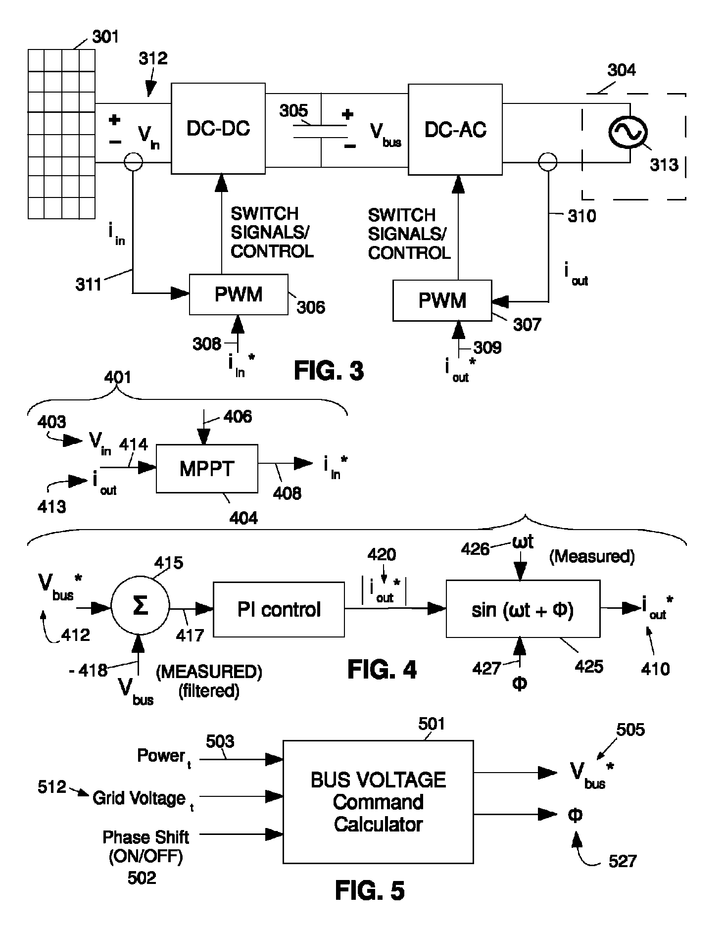
[0033]Selective control of DC and AC waveforms is provided herein. This control may be implemented in power converters, including power inverters and microinverters, and may include managing power point settings for a DC power source as well as managing DC-link bus voltages. This control may serve to modify or improve power waveforms distributed by the power converter to the public power grid or other source. The selective control may be employed in other ways and for other reasons as well.

[0034]In embodiments, the selective control of DC-link buses and DC power sources may be carried out with real-time calculations as well as with calculations made beforehand, stored, and later retrieved through the use of a look up table. Whether calculated in real-time or otherwise, phase angle settings and preferred bus voltage minimums may be considered to provide peak or improved power performance for converters or other devices employing the invention. Still further, in embodiments, selected ...


PUM


Abstract

Processes, machines, and articles of manufacture that may management power conversion as provided. This may include circuit topology or management that serves to improve power conversion efficiency from a DC waveform to an AC waveform. This circuit topology or management may include considering and managing the voltage across a DC-link capacitive bus and the phase angle output of an AC waveform in order to influence or improve power conversion characteristics or efficiency.

Description

BACKGROUND[0001]The present invention relates to power converter control, and more specifically to processes, machines, and manufactures, directed to managing, adjusting, or otherwise influencing power converter bus voltages or currents and AC output waveforms.[0002]The relationship between AC voltages and currents is load dependent. When there is no shift in waveform timing between an AC voltage and the related AC current the phase shift is said to be zero. When there is a shift in waveform timing between an AC voltage and the related AC current the phase shift can be represented in terms of positive or negative degrees where the degrees are indicative of the amount of difference in timing.[0003]When no system phase shift is measured, e.g., a 0° system phase shift, it is as if the current is passing through a simple resistor and the system is said to be at a unity power factor. When a phase shift other than 0° is measured, there is a shift in waveform timing between the voltage and...

Claims


Application Information

Patent Timeline
Patent Type & Authority Patents(United States)
IPC IPC(8): H02M1/12H02M1/14
CPCH02M7/48H02J3/383H02J3/44H02M2001/007Y02E10/563H02J2300/24H02J3/381Y02E10/56H02M1/007
Inventor CHAPMAN, PATRICK, L.
Owner ENPHASE ENERGY
Why Eureka
Eureka Blog
Learn More