
Robot

a robot and robot technology, applied in the field of robots, can solve the problems of limiting the angle and complicating the shape, and achieve the effect of increasing the flexibility of a position and reducing the volume of the operator's jointed arm moving outside the operating range of the operator's jointed arm

Inactive Publication Date: 2014-07-01
SEIKO EPSON CORP
View PDF11 Cites 8 Cited by
  • Summary
  • Abstract
  • Description
  • Claims
  • Application Information

AI Technical Summary

Benefits of technology

The invention provides a robot with a folded jointed arm that can reduce the space it occupies when folded. The robot has a mechanism that allows the second arm to be bent towards the first arm and part of the first turning mechanism and second bending and stretching mechanism to be housed in the recess of the first arm. This reduces the space occupied by the jointed arm when folded. The rotation axis of the second turning mechanism is offset with respect to the rotation axis of the first turning mechanism, increasing the flexibility of the position of the end effector. The robot also has a clearance portion preventing collisions between the first and second arms. The invention also allows for the operation of only one jointed arm while reducing the space occupied by the other jointed arm.

Problems solved by technology

Here, when the first arm is formed of, for example, a member which is linear from the base end to the tip, a collision of the second arm with the first arm may limit the angle of rotation at which the second arm is rotated toward the first arm and complicate the shape of the second arm to house the second bending and stretching mechanism in the housing recessed portion of the first arm, for example.

Method used


Image

  • Robot
  • Robot
  • Robot

Examples


Embodiment Construction

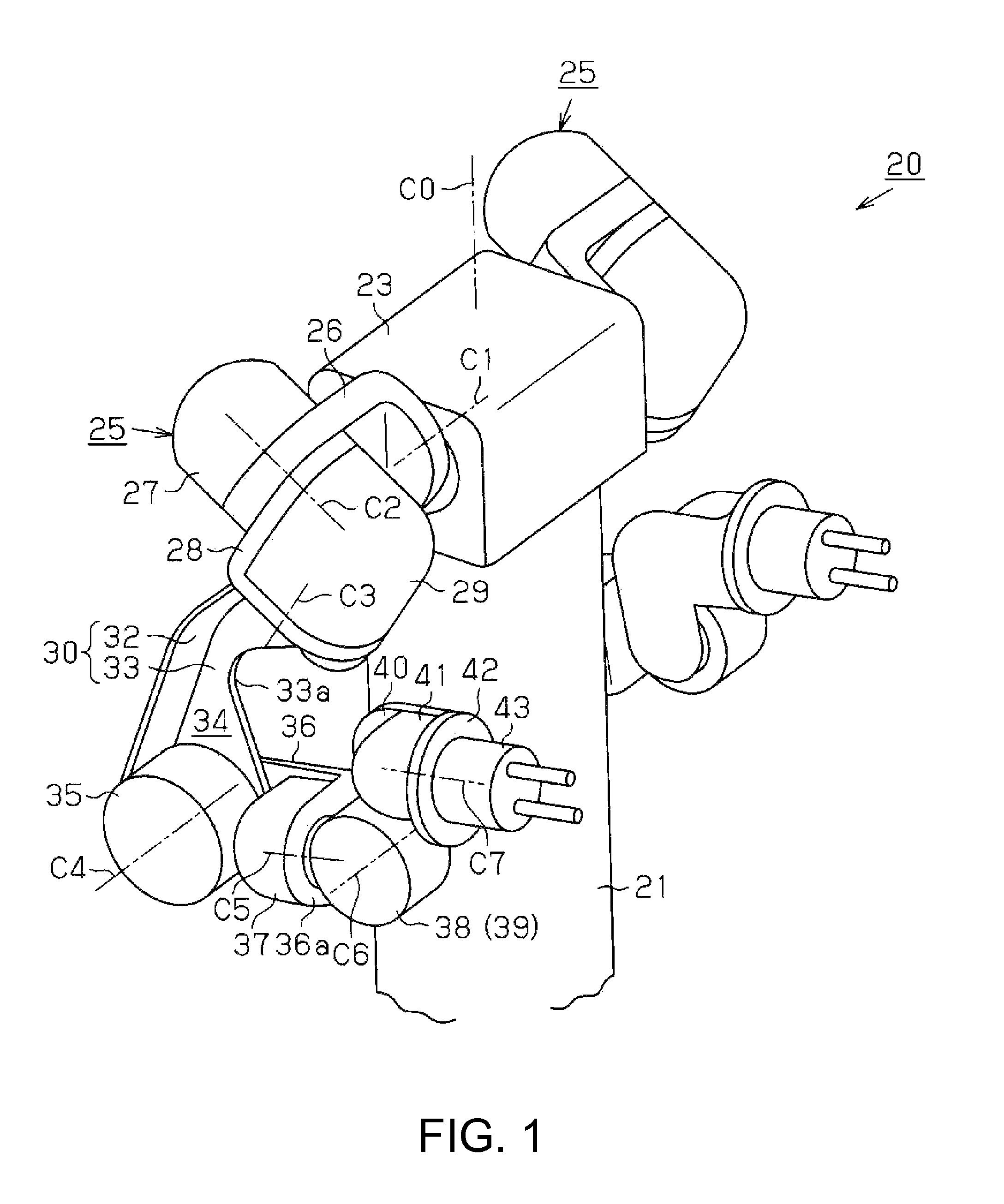
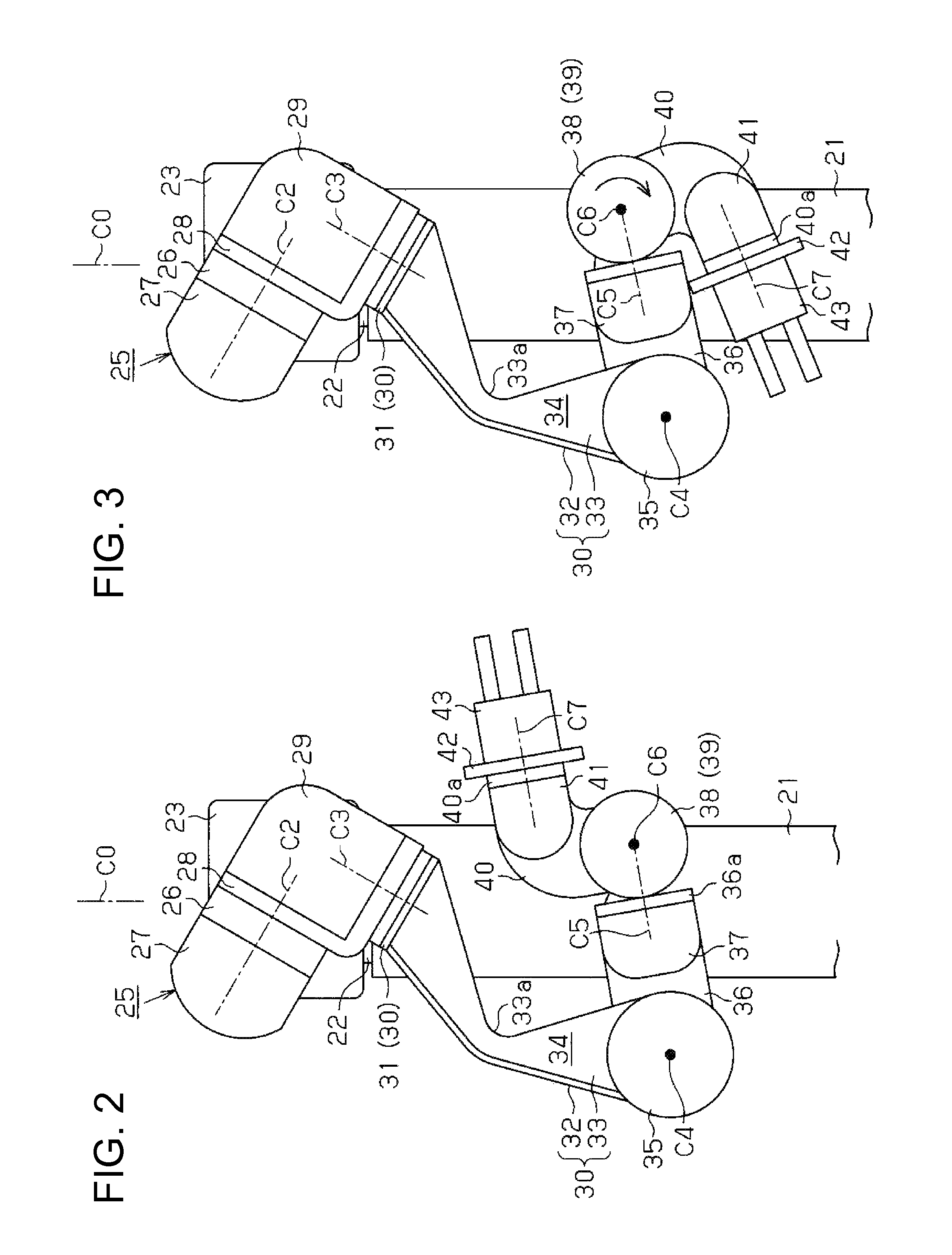
[0021]Hereinafter, an embodiment of a robot according to the invention will be described with reference to FIGS. 1 to 5. FIG. 1 is a perspective view showing an overall structure of the robot and shows a basic position of a robot 20.

[0022]As shown in FIG. 1, the robot 20 has a cylindrical base section 21 secured to an unillustrated pedestal. To an upper end of the base section 21, a body 23 that is rotatable with respect to the base section 21 about a rotation axis C0 is joined by a joint mechanism 22 having an unillustrated servomotor etc. To both sides of the body 23, a pair of jointed arms 25 is joined by unillustrated joint mechanisms disposed inside the body 23. The pair of jointed arms 25 is rotatable with respect to the body 23 about a rotation axis C1 perpendicular to the rotation axis C0. Hereinafter, the structures of the jointed arms 25 of the robot 20 will be described. Since the jointed arms 25 joined to both sides of the body 23 have symmetrically identical structures ...


PUM


Abstract

A jointed arm has an upper arm member joined to a second shoulder member, a first forearm member joined to the upper arm member by a first bending and stretching mechanism, and a wrist member joined to the first forearm member by a second bending and stretching mechanism, the first forearm member has a first turning mechanism that rotates the second bending and stretching mechanism, a hand section is joined to the wrist member by a second turning mechanism, and the rotation axes of the first and second turning mechanisms are offset. The upper arm member has a housing recessed portion that houses part of the first forearm member, part of the first turning mechanism, and part of the second bending and stretching mechanism in a state in which the first forearm member bends toward the upper arm member and the wrist member bends toward the first forearm member.

Description

BACKGROUND[0001]1. Technical Field[0002]The present invention relates to a robot provided with a jointed arm having a plurality of joints.[0003]2. Related Art[0004]In recent years, the movement toward automating the operations that had been performed by a worker on an object to be worked on by introducing a robot provided with a jointed arm in an assembly line has become active in manufacturing industries. For example, JP-A-2007-118177 (Patent Document 1), as the above-described robot discloses a dual arm robot provided with jointed arms, each being formed of a plurality of arms joined by a joint mechanism, the jointed arms provided on both sides of a body which is supported on a base and is rotatable with respect to the base. Such a robot performs an operation in accordance with an end effector attached to the tip of the jointed arm on an object to be worked on which is placed in a working space of the robot.[0005]Incidentally, the range of operations performed by the worker in the...

Claims


Application Information

Patent Timeline
Patent Type & Authority Patents(United States)
IPC IPC(8): B25J9/00B25J18/00B25J17/02B25J17/00B25J9/06
CPCB25J17/00B25J9/06B25J18/005B25J9/0087Y10S901/15B25J18/02B25J9/0027Y10S901/28Y10T74/20329Y10T74/20305Y10T74/20335
Inventor KIRIHARA, DAISUKEHOSHINO, SHINGO
Owner SEIKO EPSON CORP
Learn More