Universal non-penetrating roof solar panel mounting system

Active Publication Date: 2014-07-01
OLYMPIC ENERGY SYST
View PDF36 Cites 3 Cited by
  • Summary
  • Abstract
  • Description
  • Claims
  • Application Information

AI Technical Summary

Benefits of technology

The patent describes a system for mounting solar panels on a roof using cables and arm's to hold the panels in place without needing to penetrate the roof. The cables are tensioned and hold down a vertical rail which in turn supports two horizontal rails where the panels are fixed. This system allows for easy and safe installation without damaging the roof. Technical effects include efficient and safe installation of solar panels on a roof.

Problems solved by technology

Concerns of excessive roofing material and roofing membrane penetrations pose a practical and economic burden on conventional means of securing solar photovoltaic panels (“pv panels” or “pv modules”) to buildings and other structures.
The associated cost of those parts, along with the added cost of man-power and time required for installation, contributes significantly to the high-cost of photovoltaic systems.
The hardware-heavy conventional panel mounting systems are harmful to the existing roof structure and are expensive to purchase and install.
Installers of the systems are required to climb onto roofs for extended periods—adding wear and tear to roofing materials.
Once these holes are introduced into the roofs, there is a likelihood of eventual water damage to the roof and structure interior from rain water leaking into the holes.
Other homeowners, such as renters, may want to invest in a photovoltaic system but cannot do so given the damage such a system would do to the landlord's property combined with the expense and difficulty of removing the system and re-mounting it to a subsequent dwelling.
As a result, conventional photovoltaic mounting systems are expensive, difficult to install, damaging to the structure they are installed upon, difficult and expensive to remove / replace, environmentally unsound, unappealing and / or impossible to install given roof top materials and / or age of roof top materials.
Photovoltaic systems are simply outside the reach of the vast majority of consumers.
The high cost of photovoltaic systems is a well-known deterrent to the typical consumer—even those consumers highly desirous of adding photovoltaic systems to their homes or businesses to reduce their carbon emission footprint.
As long as the cost of photovoltaic systems remains high relative to the cost of grid-supplied energy, consumers are unlikely to invest in a photovoltaic system regardless of their interest or desire for alternative, grid-free energy sources.

Method used


Image

  • Universal non-penetrating roof solar panel mounting system
  • Universal non-penetrating roof solar panel mounting system
  • Universal non-penetrating roof solar panel mounting system

Examples


Embodiment Construction

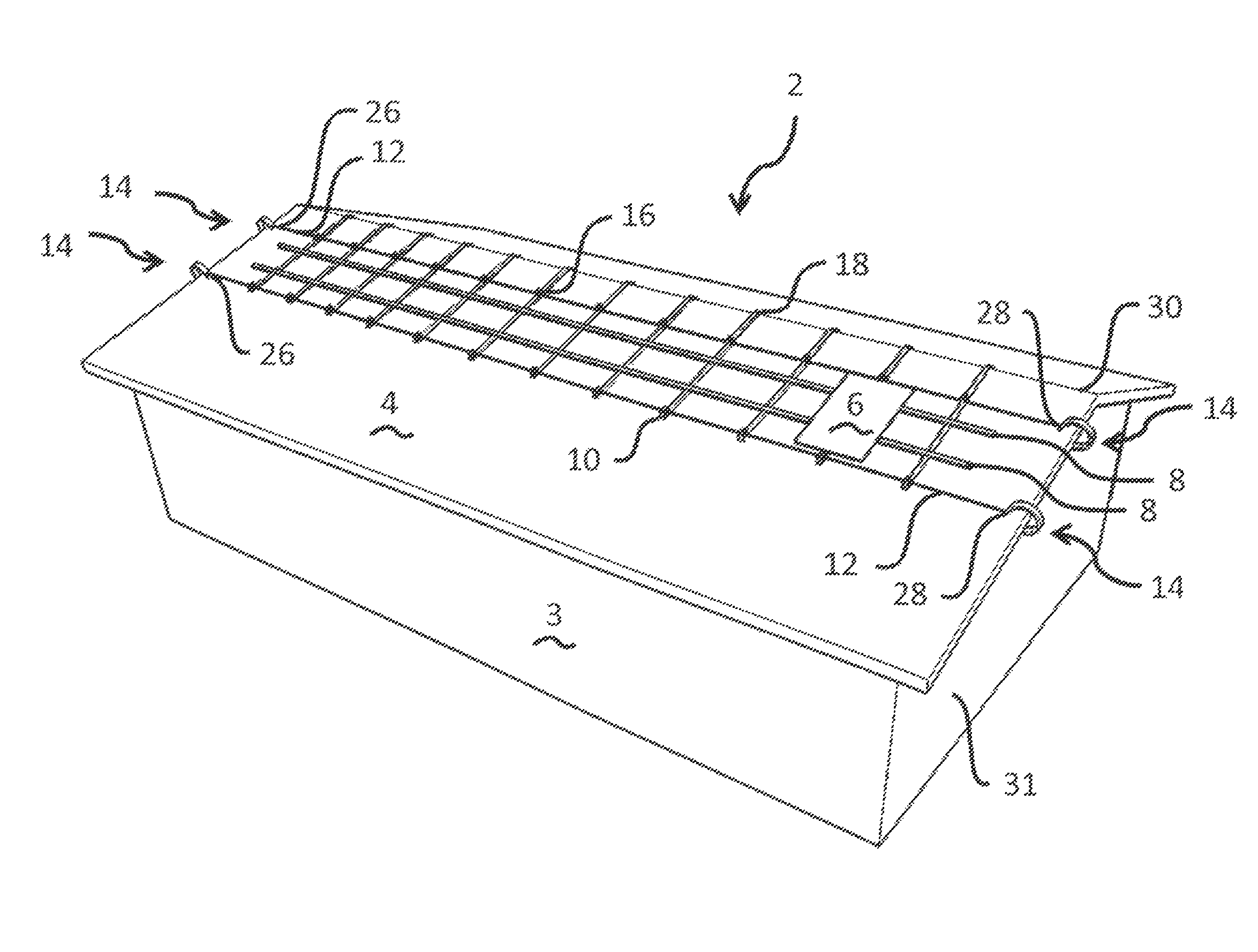
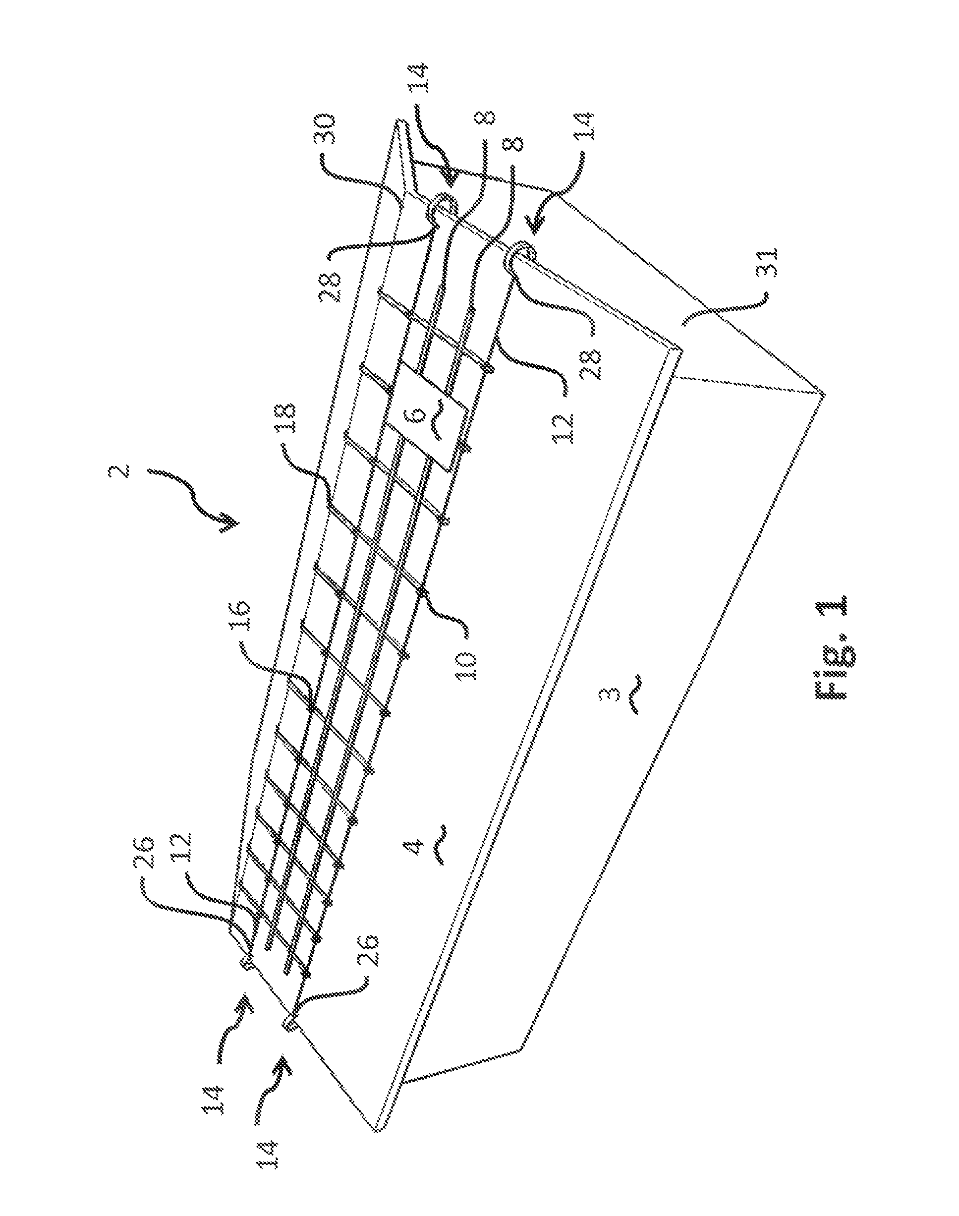
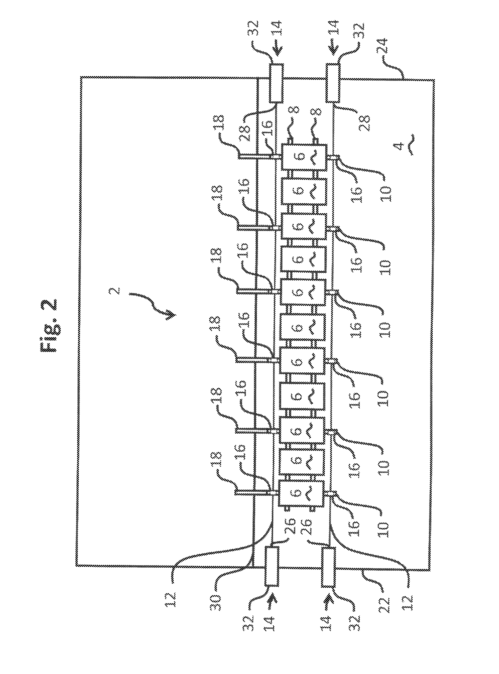
[0024]The following detailed description illustrates the invention by way of example, not by way of limitation of the scope, equivalents or principles of the invention. This description will clearly enable one skilled in the art to make and use the invention, and describes several embodiments, adaptations, variations, alternatives and uses of the invention.

[0025]In this regard, the invention is illustrated in the several figures, and is of sufficient complexity that the many parts, interrelationships, and sub-combinations thereof simply cannot be fully illustrated in a single patent-type drawing. For clarity and conciseness, several of the diagrams show in schematic, or omit, parts that are not essential in that diagram to a description of a particular feature, aspect or principle of the invention being disclosed. Thus, the best mode embodiment of one feature may be shown in one diagram, and the best mode of another feature will be called out in another diagram.

Universal Non-Penetra...


PUM


Abstract

A roof-based system for suspending photovoltaic modules, such as solar panels, relative to a roof surface without penetration of the roof surface. Cables under tension span the roof surface, with opposed ends of the cables securely mounted to generally C-shaped cable arm assemblies that wrap around the roof edge for connection via pivot joint assemblies to the underside of an overhanging eave, the immediate side wall of the structure below the roof, or directly to roof edge fascia. The system is completely contained to the roof area with no penetration of any parts through the roof surface. Vertical and horizontal rails set upon the roof surface, but not attached to the roof surface, support the weight of the photovoltaic modules attached thereto, while the cables, under tension, hold down the rails in position relative to the roof surface.

Description

CROSS-REFERENCE TO RELATED APPLICATION[0001]This is a Continuation-In-Part Application claiming priority under 35 USC 120 of U.S. patent application Ser. No. 12 / 723,871 filed Mar. 15, 2010 entitled “Tensioned Cable Solar Panel Mounting System”, said application hereby incorporated by reference.FIELD OF THE INVENTION[0002]This invention relates generally to the mounting, securing and operation of solar energy collectors such as photovoltaic panels, and more particularly to a hold down system that retains solar panels in position via cables under tension attached to roof-edge mounts universally adaptable to any type of roof edge, whether eaved, squared, angled, flat, with or without fascia, with no roof-surface penetration.BACKGROUND OF THE INVENTION[0003]Concerns of excessive roofing material and roofing membrane penetrations pose a practical and economic burden on conventional means of securing solar photovoltaic panels (“pv panels” or “pv modules”) to buildings and other structures...

Claims


Application Information

Patent Timeline
IPC IPC(8): E04D13/18
CPCF24J2/045F24J2/5205F24J2/5241F24J2/5245H02S20/20H02S20/23Y02B10/12Y02B10/20Y02E10/44Y02E10/47F24S25/61F24S25/33F24S25/50Y02E10/50Y02B10/10
Inventor CLEMENS, JONATHAN, A.
Owner OLYMPIC ENERGY SYST
Why Eureka
Try Eureka