
Patch cord assemblies, methods and systems

a technology of patch cords and assemblies, applied in the field of patch cord assemblies, can solve the problems of slow installation process, inconvenient installation, long installation time, etc., and achieve the effects of reducing handling time, convenient and efficient access, and cost-effective and efficient packaging

Active Publication Date: 2014-06-24
LEGRAND DPC LLC
View PDF27 Cites 32 Cited by
  • Summary
  • Abstract
  • Description
  • Claims
  • Application Information

AI Technical Summary

Benefits of technology

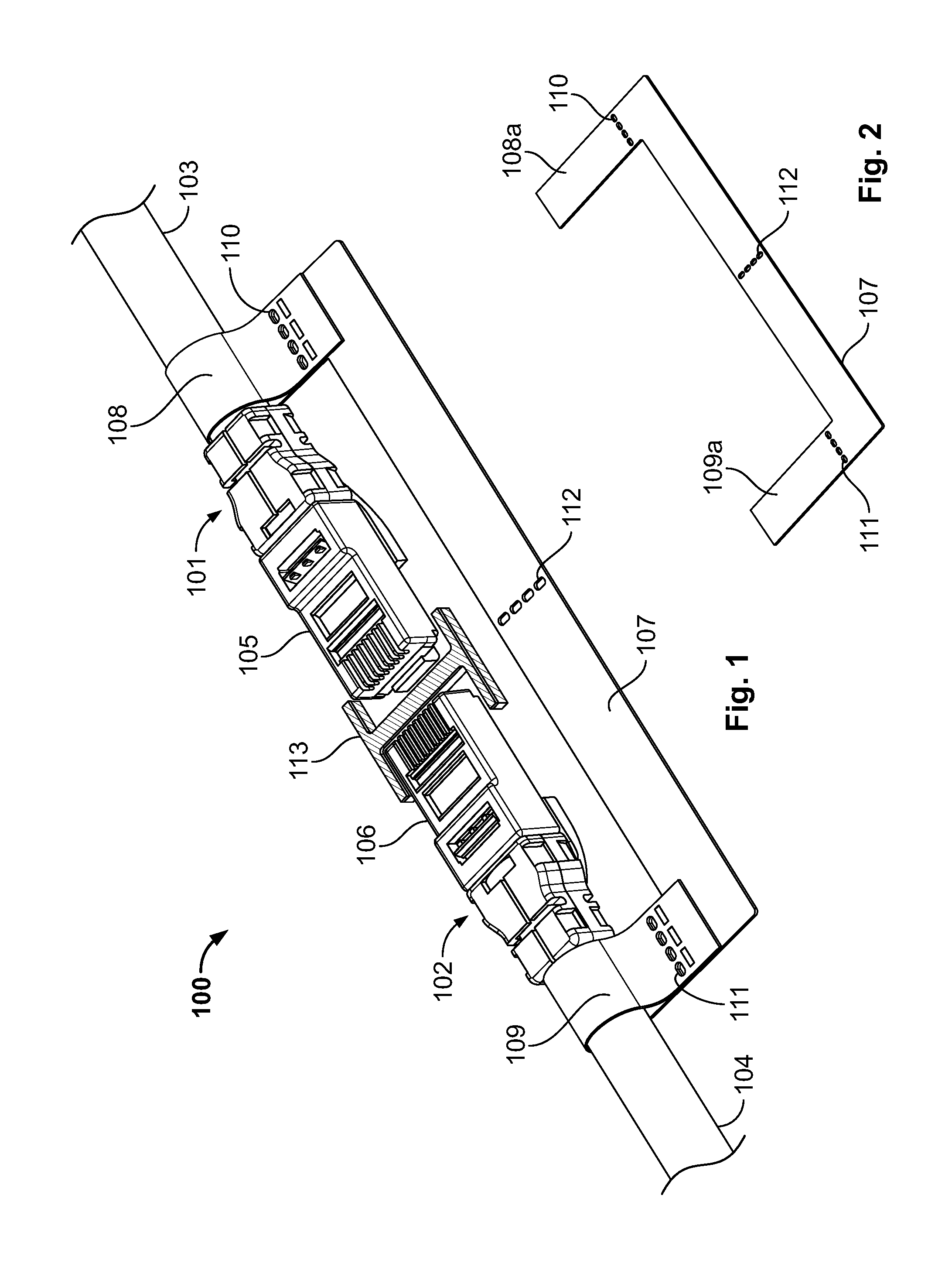
[0007]In accordance with embodiments of the present disclosure, patch cord assemblies and methods are disclosed that generally involve “daisy chain” assembly and / or packaging of patch cords. An exemplary patch cord assembly as disclosed herein generally includes a first patch cord, a second patch cord and a first coupler element that detachably secures the first patch cord relative to the second patch cord. The first patch cord generally includes a first elongated cord and a first plug mounted with respect to one end of the first elongated cord. The second patch cord generally includes a second elongated cord and a second plug mounted with respect to one end of the second elongated cord. The first coupler element is configured and dimensioned to detachably secure the first patch cord relative to the second patch cord with the first plug and the second plug in a juxtaposed relation. The exemplary embodiments of the first coupler element described herein include, but are not limited to, a first band element, a first and second band element, a sleeve element, an I-shaped coupler, first and second loops, first and second covers, a ring, first and second latches, a bit and a wedge, and the like. At the point / time of installation, the first coupler element may be removed from the first patch cord and / or the second patch cord to permit convenient and efficient access to such patch cord for field installation. The disclosed exemplary patch cord assembly, therefore, allows a more cost effective and efficient packaging, removal and installation of patch cords. In particular, the disclosed patch cord assembly addresses at least the organization of the batch of cables required by job and category, reduces the handling time prior to point-to-point connection, and minimizes the amount of refuse created from packaging.
[0009]In accordance with embodiments of the present disclosure, methods for patch cord assembly are also provided. The disclosed exemplary methods generally involve detachably securing a first patch cord relative to a second patch cord. An exemplary method of patch cord assembly as disclosed herein includes detachably securing a first patch cord relative to a second patch cord using a first coupler element, configured as a first band element. The first patch cord generally includes a first elongated cord and a first plug mounted with respect to one end of the first elongated cord. The second patch cord generally includes a second elongated cord and a second plug mounted with respect to one end of the second elongated cord. In assembling the disclosed exemplary patch cord assembly, the first band element is generally used to detachably secure the first patch cord relative to the second patch cord, generally with the first plug and the second plug in a juxtaposed relation, e.g., an opposing, spaced relation. The disclosed exemplary method of patch cord assembly, therefore, allows a more cost effective and efficient packaging, removal and installation of patch cords.
[0010]In accordance with further embodiments of the present disclosure, the first band element is generally effective to maintain the first patch cord and the second patch cord in a relatively stable configuration / orientation such that the first plug and the second plug are in confronting or opposing spaced relation. Thus, the first plug and the second plug may be positioned and maintained in a common plane by the first band element. The spacing between the first plug and the second plug ensures that the respective plugs are not damaged during storage and / or shipment, e.g., through undesirable and uncontrolled contact therebetween. In addition, the substantially planar relationship between the first and second plugs—which is maintained by the first band element—facilitates efficient “stacking” of patch cord assemblies of the present disclosure, e.g., in a shipping box or the like.
[0011]The disclosed exemplary patch cord assembly may include additional structures and / or features in connection with the detachable securement described herein. For example, the patch cord assembly may include one or more spacer elements positioned between (or at least partially between) the first and second plugs, such spacer element(s) advantageously functioning to further prevent inadvertent or undesirable contact between the first and second plugs. The spacer element(s) may also further facilitate maintenance of the first and second plugs in a substantially planar relationship. The spacer element(s) may be integrally formed with the first band element, mounted with respect to the first band element and / or separate / distinct from the first band element.

Problems solved by technology

Thus, large amounts of material are typically wasted in packaging patch cords and each patch cord must be individually removed prior to installation, thereby slowing the installation process and generally inconveniencing the installer.
In an industry where large numbers of patch cords may be required for installation at one time, individually removing patch cords from individual packages can lead to lengthy installation times.

Method used


Image

  • Patch cord assemblies, methods and systems
  • Patch cord assemblies, methods and systems
  • Patch cord assemblies, methods and systems

Examples


Embodiment Construction

)

[0058]In accordance with embodiments of the present disclosure, patch cord assemblies and associated methods disclosed herein generally involve daisy chain assembly for patch cords. An exemplary patch cord assembly as disclosed herein includes a first patch cord, a second patch cord and a first coupler element. The first patch cord includes a first elongated cord and a first plug mounted with respect to one end of said first elongated cord. The second patch cord includes a second elongated cord and a second plug mounted with respect to one end of said second elongated cord. Thus, the first coupler element detachably secures the first patch cord relative to the second patch cord with the first plug and the second plug in a juxtaposed relation.

[0059]With reference to FIG. 1, an exemplary embodiment of a patch cord assembly is depicted in accordance with the present disclosure in the form of a patch cord assembly 100. The patch cord assembly 100 generally includes a first patch cord 1...


PUM

PropertyMeasurementUnit
timeaaaaaaaaaa
structuresaaaaaaaaaa
thicknessaaaaaaaaaa

Abstract

A patch cord assembly is provided for detachably securing a first patch cord relative to a second patch cord, defined by a first patch cord that includes a first elongated cord and a first plug mounted with respect to one end of said first elongated cord, and a second patch cord that includes a second elongated cord and a second plug mounted with respect to one end of said second elongated cord. A method of patch cord assembly is provided for detachably securing a first patch cord relative to a second patch cord. A system of patch cord assembly packaging and payout is provided including a housing for packaging a patch cord assembly and at least one housing opening for paying out the at least first patch cord.

Description

CROSS-REFERENCE TO RELATED APPLICATION[0001]The present application claims priority to a provisional patent application entitled “Patch Cord Assembly and Method,” filed with the U.S. Patent and Trademark Office on Nov. 8, 2011, and assigned Ser. No. 61 / 557,108. The entire content of the foregoing provisional patent application is incorporated herein by reference.BACKGROUND[0002]1. Technical Field[0003]The present disclosure is directed generally to patch cord assemblies, associated methods and systems and, more particularly, to daisy chain patch cord assemblies, associated methods and patch cord assembly packaging and payout systems.[0004]2. Background Art[0005]Patch cords are generally used in a variety of settings to create electrical connections for communication between electronic devices, e.g., networking between switches, servers, storage devices, etc. In packaging / supplying patch cords to the trade, manufacturers generally package patch cords individually, e.g., in plastic pa...

Claims


Application Information

Patent Timeline
Patent Type & Authority Patents(United States)
IPC IPC(8): H01R13/60
CPCH01R13/60H01R24/64Y10T29/49194
Inventor PEZZETTI, JOHN B.SHEW, ROBERT SCOTTRYNASKI, CHESTER H.MOORE, GREGORY
Owner LEGRAND DPC LLC
Learn More