
Housing for an electronic or mechtronic unit including seal with pressure relief device

a technology for electronic or mechatronic units and housings, which is applied in the direction of casings/cabinets/drawers, casings/cabinets/drawers details, electrical appliances, etc., can solve the problems of dirty water reaching the interior space through the bore, damage to sensitive components, and the conventional housings of electronic and mechatronic units do not have any openings to the atmospher

Active Publication Date: 2014-06-24
ZF CV SYST EURO BV
View PDF21 Cites 0 Cited by
  • Summary
  • Abstract
  • Description
  • Claims
  • Application Information

AI Technical Summary

Benefits of technology

The present invention provides a housing for electronic or mechatronic units that has a pressure-relief device integrated in the seal between the top and bottom parts of the housing. This results in a better seal against external dirty water and allows for the rapid discharge of overpressure from the interior space to the atmosphere. The invention avoids the need for special devices such as overpressure valves, making the housing more affordable.

Problems solved by technology

However, conventional housings for electronic and mechatronic units do not have any openings to atmosphere that permit a breathing process.
The housing described in DE 10022124 A1, however, suffers from the disadvantage that dirty water can reach the interior space through the bore.
As a result, sensitive components can be damaged.

Method used


Image

  • Housing for an electronic or mechtronic unit including seal with pressure relief device
  • Housing for an electronic or mechtronic unit including seal with pressure relief device
  • Housing for an electronic or mechtronic unit including seal with pressure relief device

Examples


Embodiment Construction

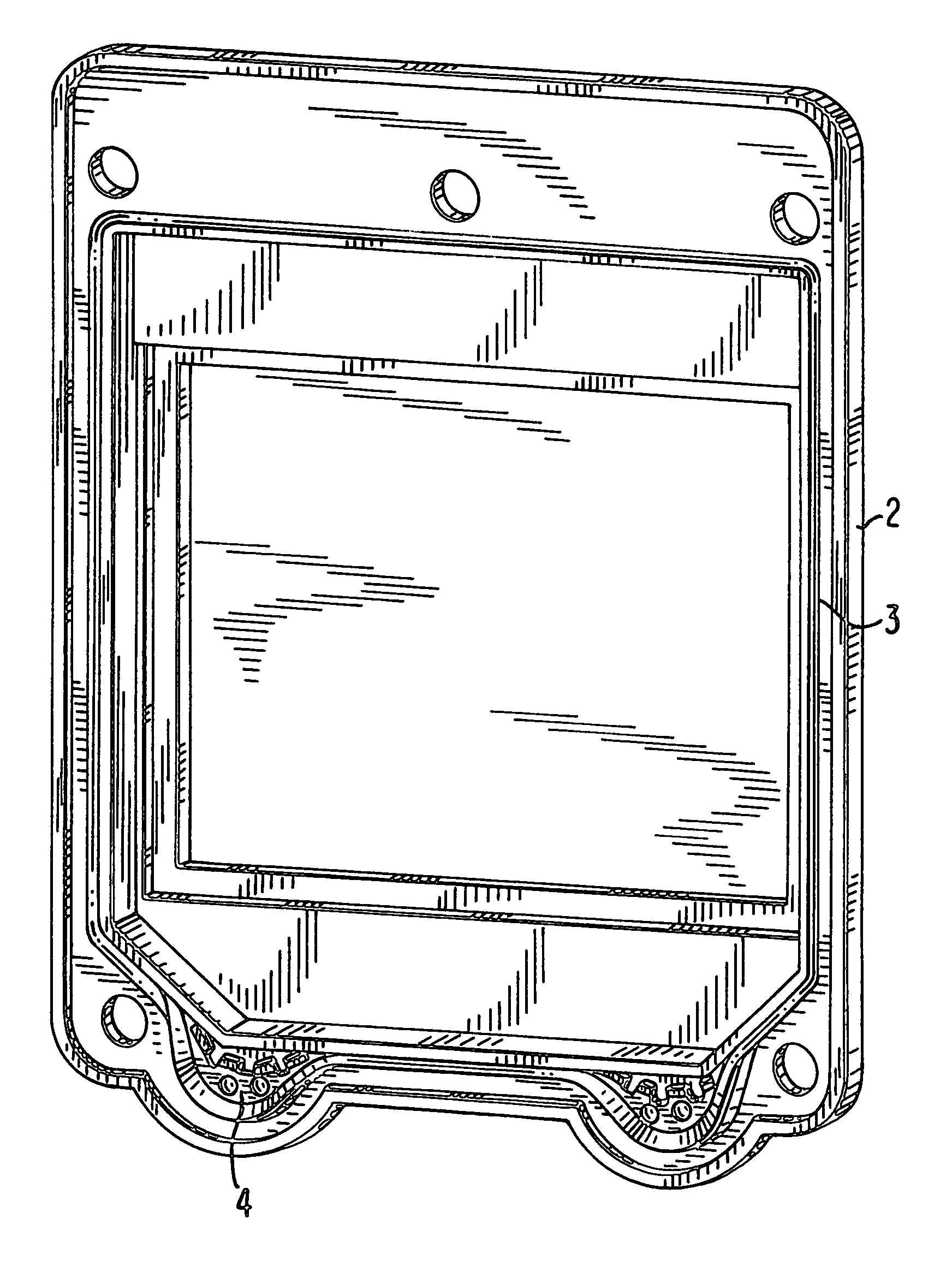
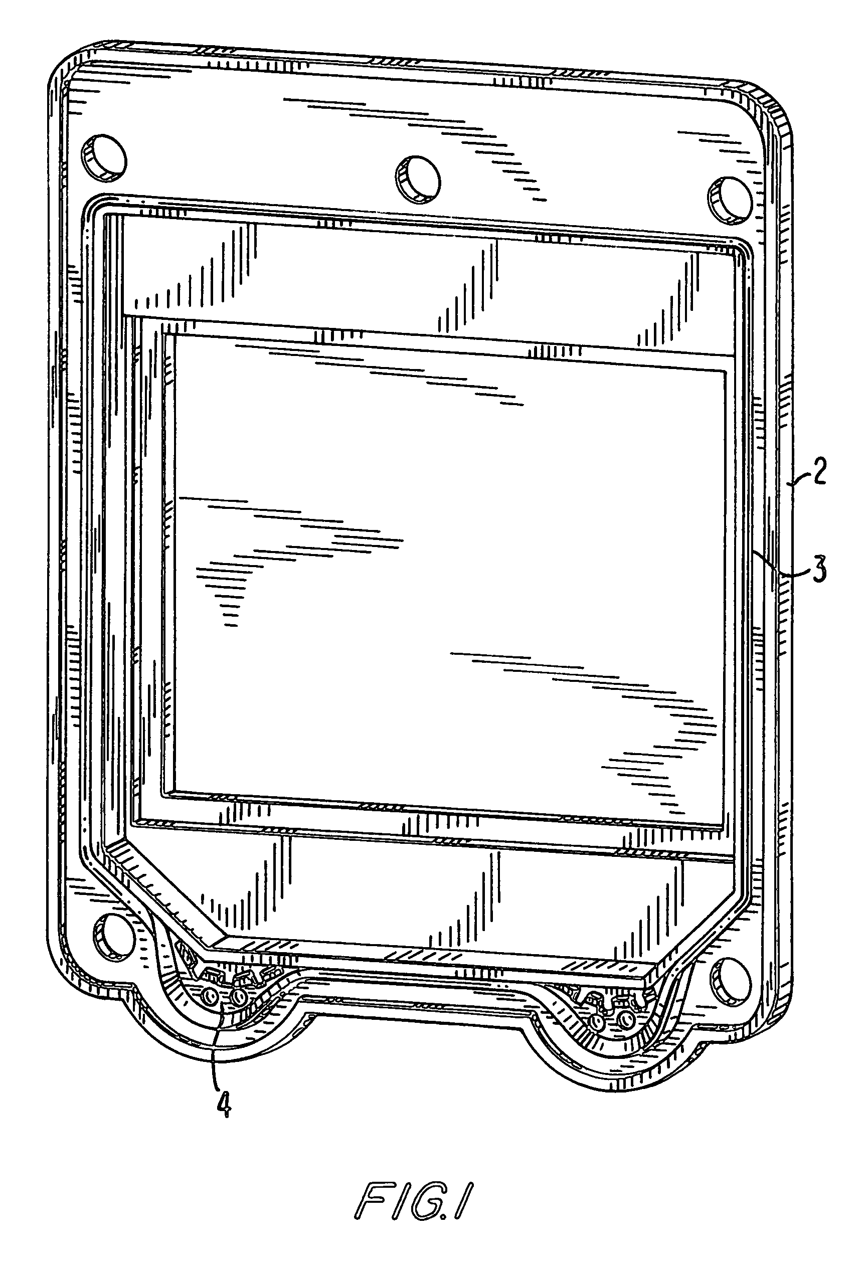
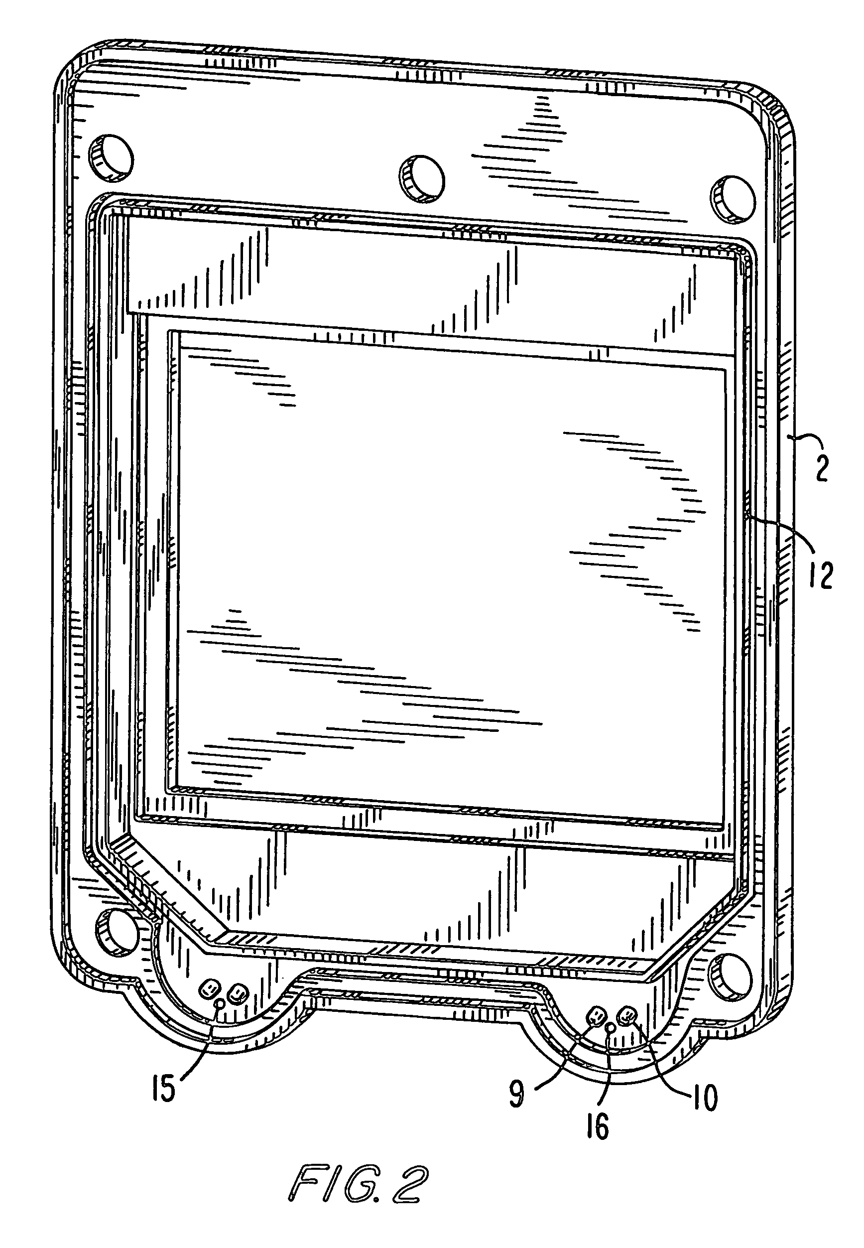
[0020]Referring to the drawing figures, where like reference numerals are used for corresponding parts, FIG. 1 is a perspective view of a “bottom” part (2) of a housing (1) for an electronic unit or a mechatronic unit. An encircling seal (3) is shown lodged in a groove (12) defined in the housing (compare with FIG. 2).

[0021]Although housing (1) is generally designed for installation and use in vertical position with a pressure-relief device (4) disposed at the bottom, (see FIG. 8), for ease of explanation, the terms “top” part and “bottom” part of the housing will hereinafter be used to refer to the housing parts (17) and (2), respectively, shown mounted side-by-side in FIG. 8. Parts (17) and (2) may also be referred to as “side” parts.

[0022]Seal (3) is preferably formed from an elastic material, such as rubber or plastic, for example. Mechanical, pneumatic and electronic components can be disposed in known manner in the interior of housing (1). Seal (3) is provided with two pressur...


PUM


Abstract

A device housing, especially for accommodating an electronic unit or a mechatronic unit, has parts which are sealed against one another in assembled condition via an encircling, stationary seal. At least one pressure-relief device is integrated into the seal for admission of air into the housing. The seal is formed at least in part as a lip that opens under overpressure conditions inside the housing. To allow any water that has penetrated to flow away, the housing is mounted vertically, with the pressure-relief device disposed at the bottom.

Description

BACKGROUND OF THE INVENTION[0001]The present invention relates generally to a device housing, and, more particularly, to a housing for an electronic unit or a mechatronic unit. The present invention has particular application in vehicle systems.[0002]Large numbers of housings for electronic and mechatronic units are routinely manufactured, and so they must be capable of being manufactured at a favorable cost. In addition, however, adequate protection of the electronic or mechatronic unit disposed in the housing must also be ensured, especially for service under difficult ambient conditions, such as in motor vehicles. In particular, uncontrolled ingress of water into the housing must be prevented. For this purpose, the housing is typically equipped with an encircling, statically designed, elastic seal, which seals a top part against a bottom part of the housing in the assembled condition.[0003]Furthermore, it is advantageous for the housing to be capable of controlled air exchange wi...

Claims


Application Information

Patent Timeline
Patent Type & Authority Patents(United States)
IPC IPC(8): B65D51/16B65D6/28H05K5/00H05K5/02H05K5/06
CPCH05K5/061H05K5/068
Inventor BORNHOF, HANS-ULRICHDIEKMEYER, HEINRICHEGGEBRECHT, DETLEV
Owner ZF CV SYST EURO BV
Learn More