
Mask frame assembly

a mask and frame technology, applied in the field of mask frame assembly, can solve the problems of difficult to obtain a high efficiency light emission from the deposition structure, difficult to achieve precise patterning, and severe sagging phenomenon of the center portion of the fmm due to the weight of the fmm itself, so as to prevent or reduce the generation of wrinkles in the mask

Active Publication Date: 2014-06-24
SAMSUNG DISPLAY CO LTD
View PDF20 Cites 10 Cited by
  • Summary
  • Abstract
  • Description
  • Claims
  • Application Information

AI Technical Summary

Benefits of technology

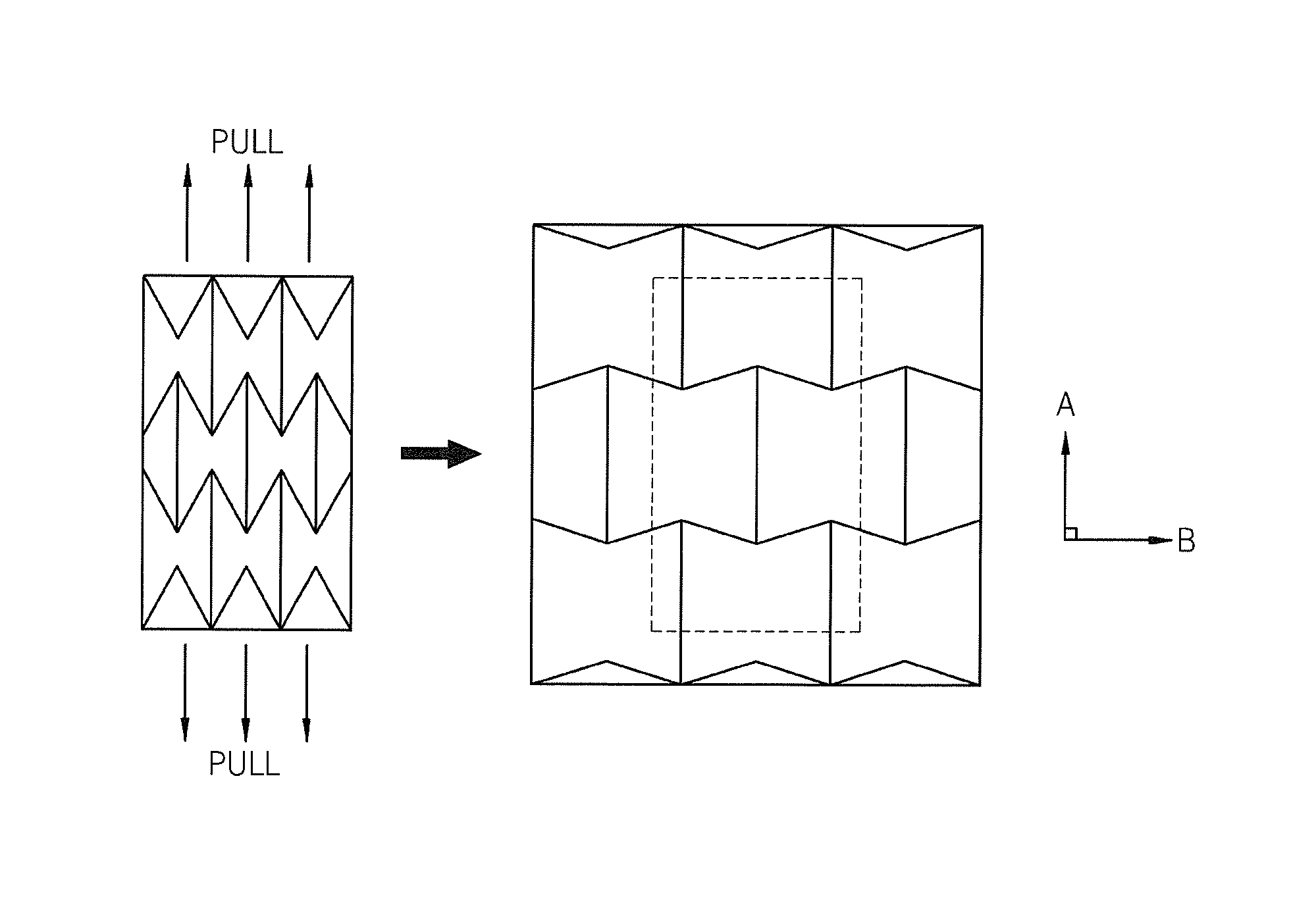
The solution effectively prevents wrinkle generation and maintains precise patterning during deposition by applying a tension force in the widthwise direction, addressing the sagging and contraction issues of the mask frame assembly.

Problems solved by technology

However, since it is difficult to obtain a high efficiency light emission from the deposition structure, an intermediate layer, such as an electron injection layer, an electron transport layer, a hole transport layer, and a hole injection layer, between each electrode and the light-emitting layer needs to be selectively and additionally inserted.
As the size of the FMM increases, an etching error in forming a thin film pattern increases and a sagging phenomenon at the center portion of the FMM due to the weight of the FMM itself becomes severe.
As such, when the wrinkles are generated, the mask is not closely attached to the substrate in some positions so that precise patterning may not be possible.
However, when the mask is attached directly to the frame without being pulled, it is not possible to form a precise pattern because of the mask sagging phenomenon described above.

Method used


Image

  • Mask frame assembly
  • Mask frame assembly
  • Mask frame assembly

Examples


Embodiment Construction

[0028]Some exemplary embodiments will now be described more fully hereinafter with reference to the accompanying drawings, wherein like reference numerals refer to the like elements throughout. Embodiments of the present invention may be embodied in different forms and should not be construed as limited to the exemplary embodiments illustrated and set forth herein. Rather, these exemplary embodiments are provided by way of example for understanding of the invention and to convey the scope of the invention to those skilled in the art.

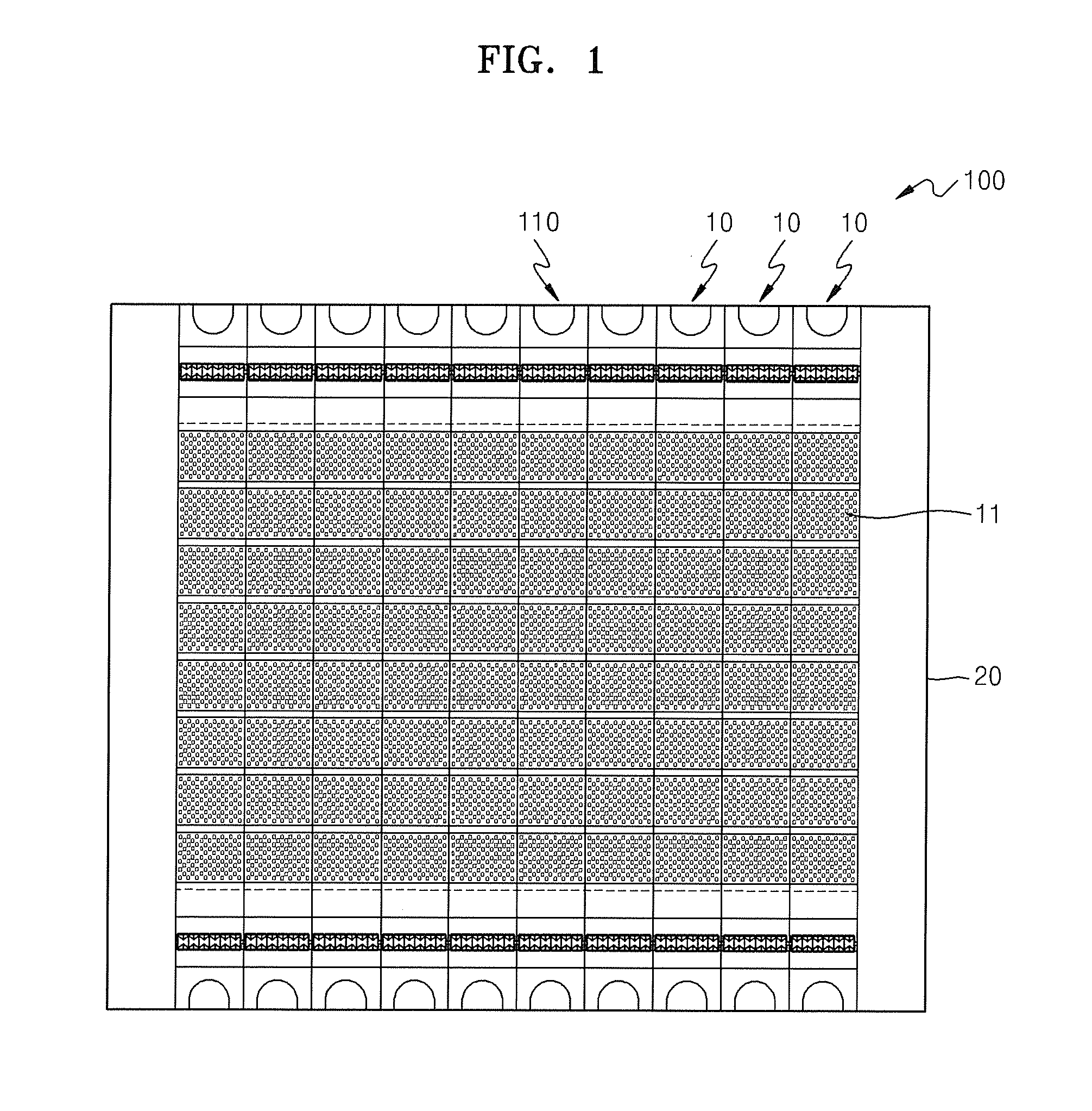
[0029]FIG. 1 is a plan view of a mask frame assembly 100 according to an exemplary embodiment of the present invention. Referring to FIG. 1, the mask frame assembly 100 according to one exemplary embodiment includes a frame 20 and a mask 110 including a plurality of split mask portions 10, each split mask portion 10 having both end portions fixed to the frame 20.

[0030]The frame 20 forms an outside frame of the mask frame assembly 100 and, in one embodime...


PUM

PropertyMeasurementUnit
thicknessaaaaaaaaaa
forceaaaaaaaaaa
depositionaaaaaaaaaa

Abstract

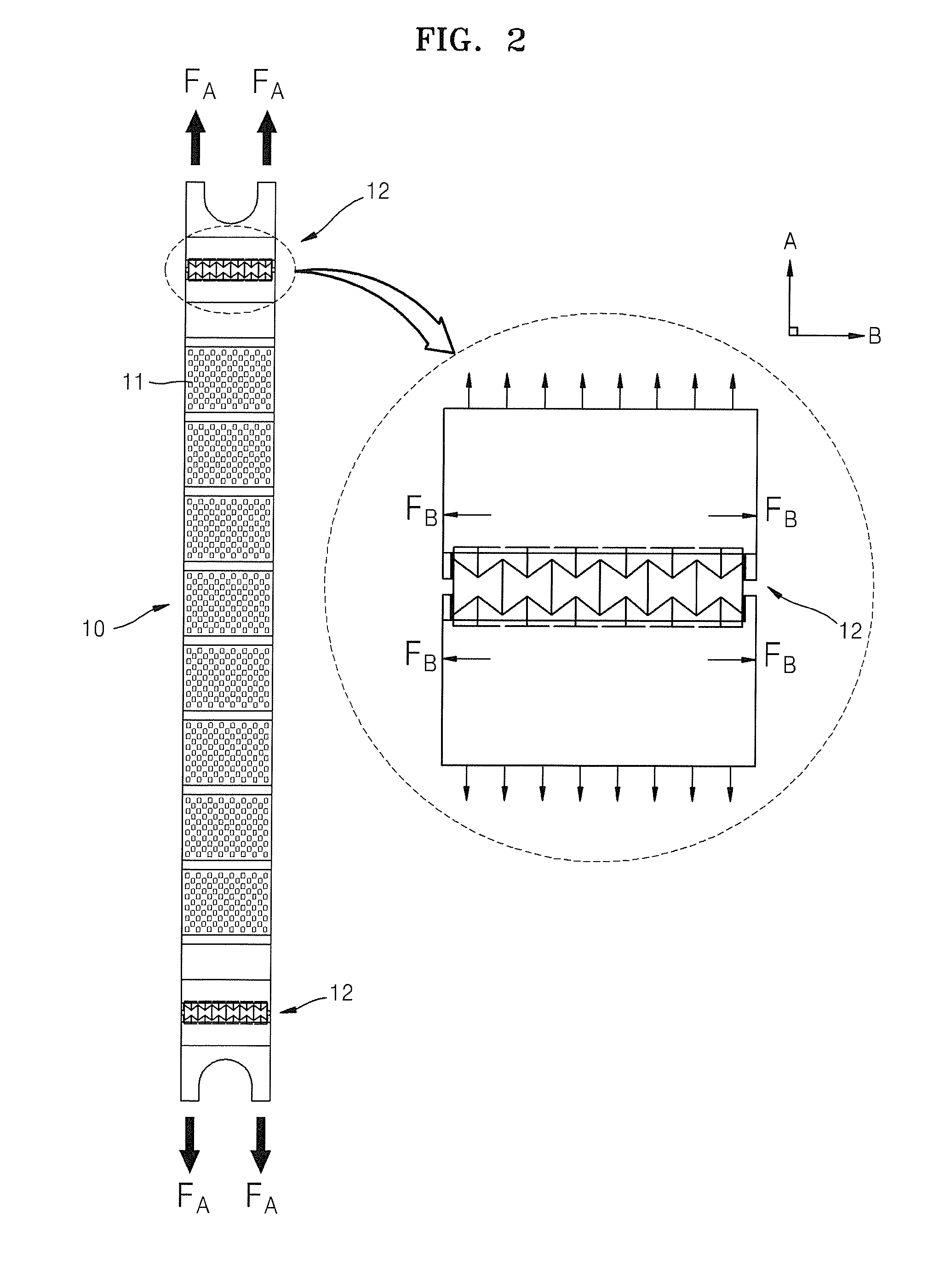
A mask frame assembly includes a frame, a mask having a deposition pattern and being installable on the frame in a state of being pulled by a first tension force in a first direction, and a tension force applying portion in the mask and configured to apply a second tension force in a second direction that is perpendicular or substantially perpendicular to the first direction.

Description

CROSS-REFERENCE TO RELATED APPLICATION[0001]This application claims the benefit of Korean Patent Application No. 10-2010-0040231, filed on Apr. 29, 2010, in the Korean Intellectual Property Office, the disclosure of which is incorporated herein in its entirety by reference.BACKGROUND[0002]1. Field[0003]Aspects of embodiments of the present invention relate to a mask frame assembly used for deposition of a thin film.[0004]2. Description of the Related Art[0005]In general, an organic light emitting display exhibits a wide viewing angle, superior contrast, and fast response speeds. The organic light emitting display produces colors by injecting holes and electrons respectively in an anode and a cathode and combining the holes and electrons in a light-emitting layer. The organic light emitting display has a deposition structure in which the light-emitting layer is inserted between the anode and the cathode. However, since it is difficult to obtain a high efficiency light emission from t...

Claims


Application Information

Patent Timeline
Patent Type & Authority Patents(United States)
IPC IPC(8): B05C11/00C23C14/04
CPCC23C14/042C23C14/04
Inventor LEE, CHOONG-HOLEE
Owner SAMSUNG DISPLAY CO LTD
Learn More