
Gas separator with improved flow path efficiency

a gas separator and flow path technology, applied in the direction of positive displacement liquid engine, separation process, wellbore/well accessories, etc., can solve the problems of gas locking, head degradation, and notable increase in the amount of pumping head needed in the separator chamber, and achieve the effect of improving flow path efficiency

Active Publication Date: 2014-06-10
BAKER HUGHES INC
View PDF10 Cites 9 Cited by
  • Summary
  • Abstract
  • Description
  • Claims
  • Application Information

AI Technical Summary

Benefits of technology

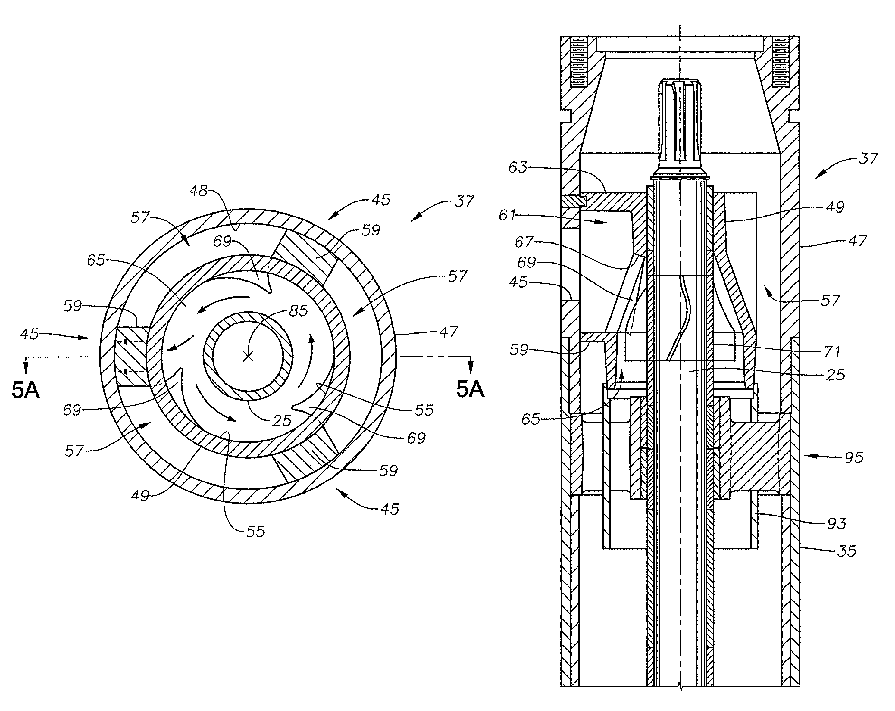
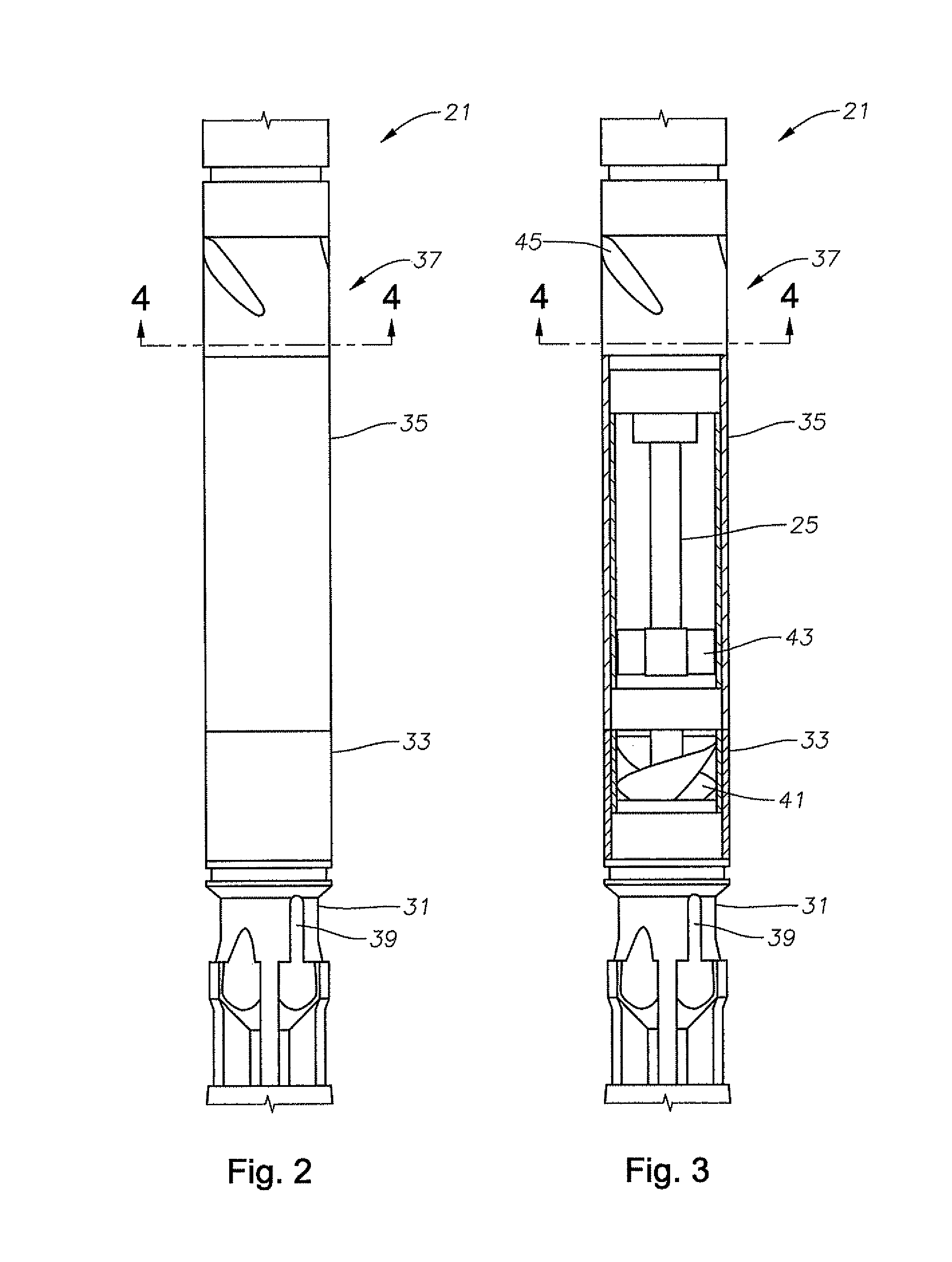
The present invention provides an improved gas separator for use in submersible pump assemblies. The gas separator has a venting portion that directs gas into the intake of the pump and guides the lighter fluid towards a venting port. The design of the gas separator has increased flowpath efficiency, reducing the total pumping head required to lift fluid to the surface. The invention also includes a slinger with modified blades that increase the flow rate of high gas content fluid out of the gas separator and into the wellbore, further increasing efficiency.

Problems solved by technology

ESPs are designed to handle liquid and will suffer from head degradation and gas locking in the presence of a high percentage of free gas.
This pressure increase causes a notable increase in the amount of pumping head needed within the separator chamber.

Method used


Image

  • Gas separator with improved flow path efficiency
  • Gas separator with improved flow path efficiency
  • Gas separator with improved flow path efficiency

Examples


Embodiment Construction

[0022]The present invention will now be described more fully hereinafter with reference to the accompanying drawings which illustrate embodiments of the invention. This invention may, however, be embodied in many different forms and should not be construed as limited to the illustrated embodiments set forth herein. Rather, these embodiments are provided so that this disclosure will be thorough and complete, and will fully convey the scope of the invention to those skilled in the art. Like numbers refer to like elements throughout, and the prime notation, if used, indicates similar elements in alternative embodiments.

[0023]In the following discussion, numerous specific details are set forth to provide a thorough understanding of the present invention. However, it will be obvious to those skilled in the art that the present invention may be practiced without such specific details. Additionally, for the most part, details concerning ESP operation, construction, and the like have been o...


PUM

PropertyMeasurementUnit
lengthaaaaaaaaaa
momentumaaaaaaaaaa
inner diameteraaaaaaaaaa

Abstract

A gas separator having an improved flowpath for lighter fluids having a higher concentration of gas decreases total pumping head for an ESP assembly. The ESP assembly includes a rotary primary pump, a motor coupled to the primary pump for driving the pump, a seal assembly between the primary pump and the motor, and a gas separator between the seal assembly and the primary pump. An outlet of the gas separator feeds an intake of the primary pump, and a rotating shaft operationally couples the primary pump to the motor and passes through the seal assembly and the gas separator. The gas separator contains a venting portion, and a diverter positioned within the venting portion having diverter guide vanes formed in a flowpath of the lighter fluid for aiding in a directional change of fluid momentum. A slinger is positioned within the diverter for impelling fluid through the venting port.

Description

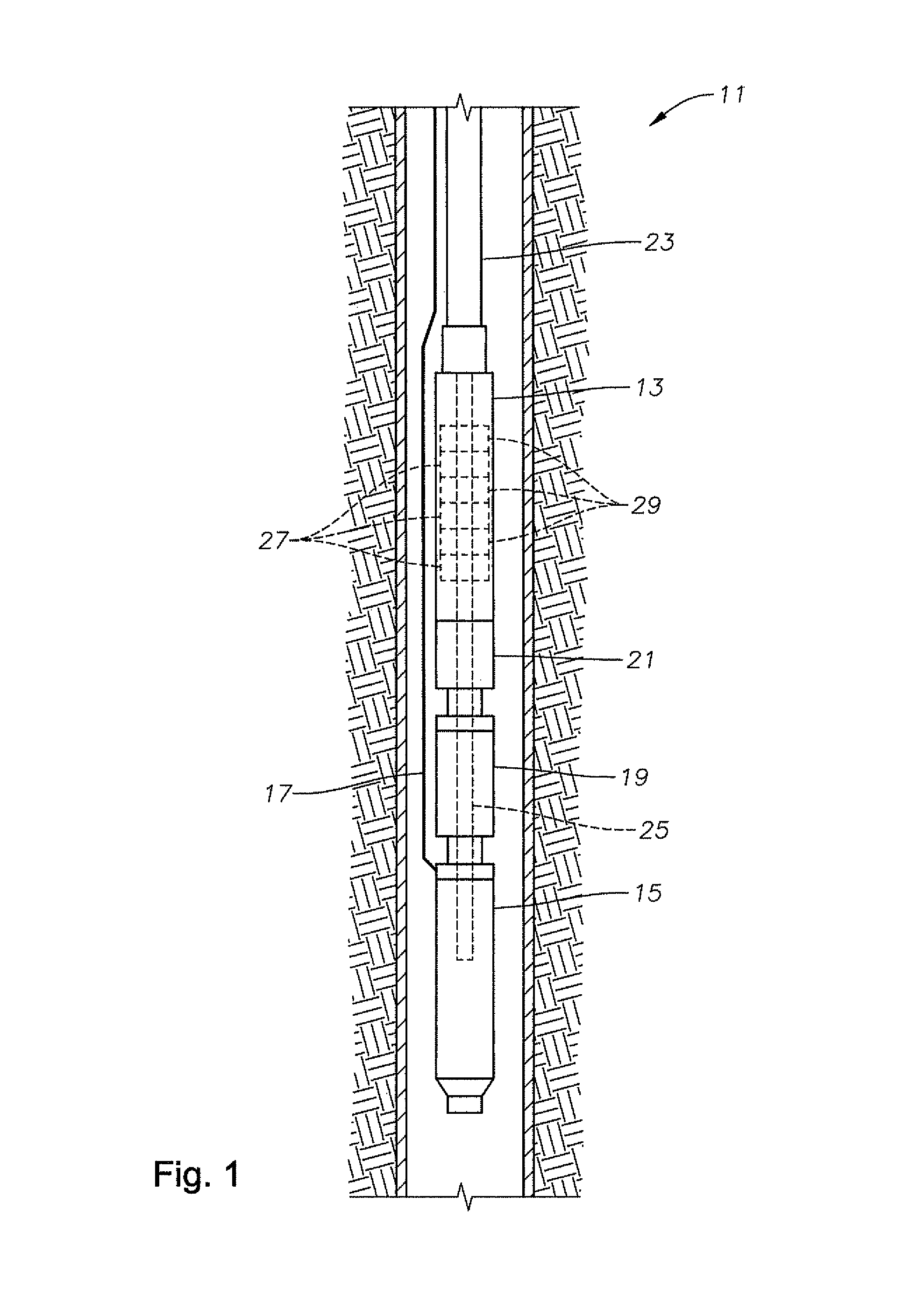
BACKGROUND OF THE INVENTION[0001]1. Field of the Invention[0002]This invention relates in general to electric submersible pumps (ESPs) and, in particular, to a gas separator with improved flow path efficiency.[0003]2. Brief Description of Related Art[0004]Electric submersible pump (ESP) assemblies are disposed within wellbores and operate immersed in wellbore fluids. The ESP assemblies generally include a pump portion and a motor portion. Generally, the motor portion is downhole from the pump portion, and a rotatable shaft connects the motor and the pump. The rotatable shaft may be one or more shafts operationally coupled together. The motor rotates the shaft that, in turn, rotates components within the pump to lift fluid through a production tubing string to the surface. The ESP assembly may also include one or more seal sections coupled to the shaft between the motor and pump. In some embodiments, the seal section connects the motor shaft to the pump intake shaft. The seal section...

Claims


Application Information

Patent Timeline
Patent Type & Authority Patents(United States)
IPC IPC(8): F04B39/00B01D45/12E21B43/00
CPCF04D29/445F04D29/4273F04D13/10F04D29/708F04D9/003
Inventor BROWN, DONN J.WILSON, BROWN LYLE
Owner BAKER HUGHES INC
Learn More