
Fall protection cage with adjustable outboard upright

a technology of outboard uprights and cages, which is applied in the direction of bridges, loading/unloading, construction, etc., can solve the problems of inability to compensate, inconvenient use, and insufficient clearance height at the outboard side of the enclosure,

Active Publication Date: 2014-06-10
SAM CARBIS ASSET MANAGEMENT
View PDF19 Cites 20 Cited by
  • Summary
  • Abstract
  • Description
  • Claims
  • Application Information

AI Technical Summary

Benefits of technology

The present invention relates to a selectively deployable fall protection enclosure for accessing the tops of rolling stock, such as tank cars. The invention addresses the issue of inadequate clearance between the enclosure and the rolling stock when the enclosure is raised to its stored position, which can lead to contact between the enclosure and the rolling stock. The invention provides a solution to this problem by designing the enclosure to compensate for the leaning or deflection of its outboard side, which is caused by factors such as loading rack tolerances or fabrication tolerances. The invention includes a selectively deployable fall protection cage that can be raised and lowered to provide increased levels of fall protection. The invention also includes a method for accessing the tops of rolling stock using the selectively deployable fall protection enclosure.

Problems solved by technology

There are many instances in which the clearance height at the outboard side of the enclosure can become inadequate to avoid coming into contact with the rolling stock or the equipment used to move the rolling stock.
Such instances can arise when the outboard side of the enclosure leans or that deflects due to the size and / or weight of the enclosure.
However, because both the size and the weight of the enclosures has increased greatly to provide an increased level of fall protection, designs that compensate for the anticipated leaning of these much larger and heavier enclosures are very costly and / or otherwise impractical.

Method used


Image

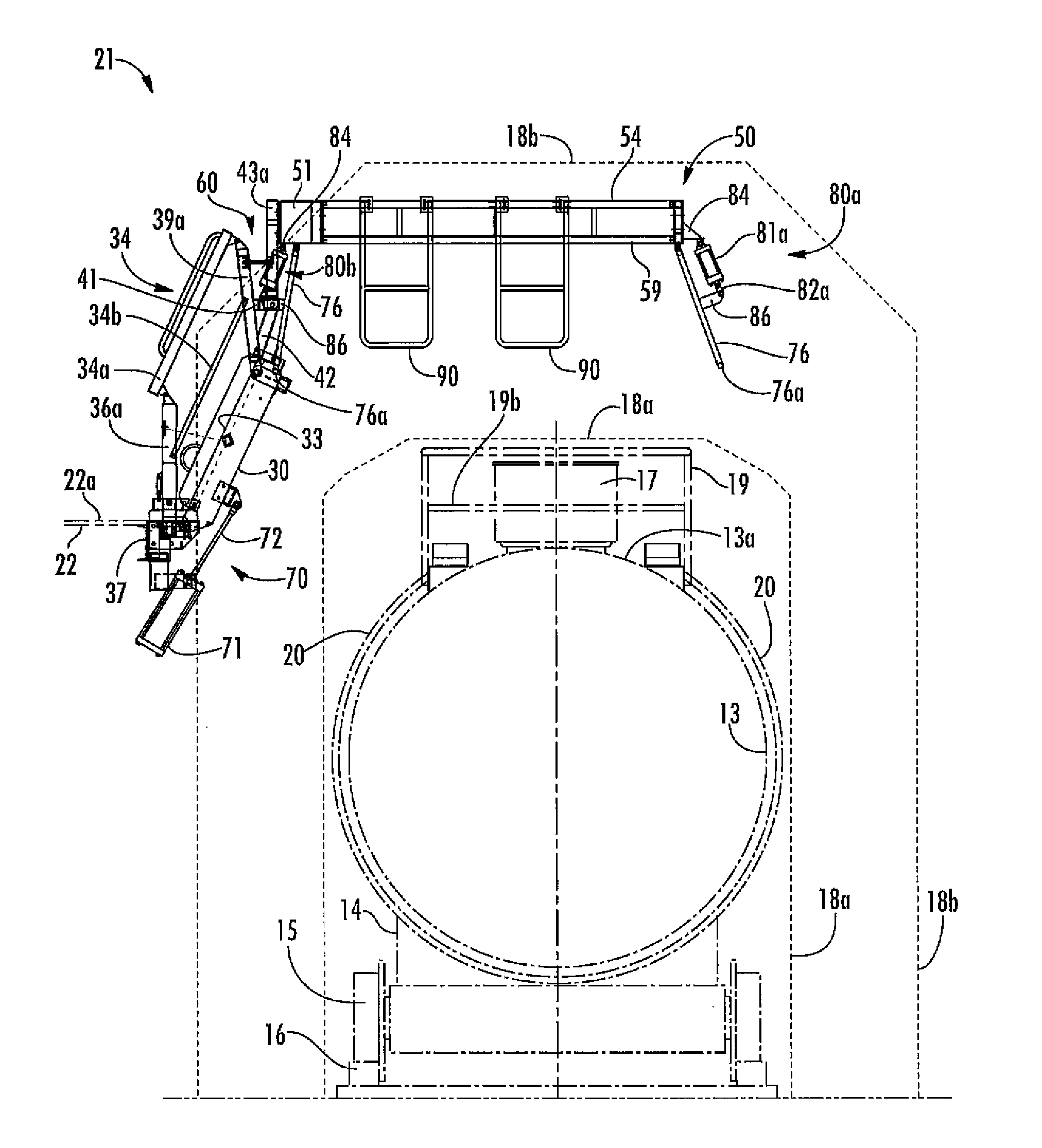
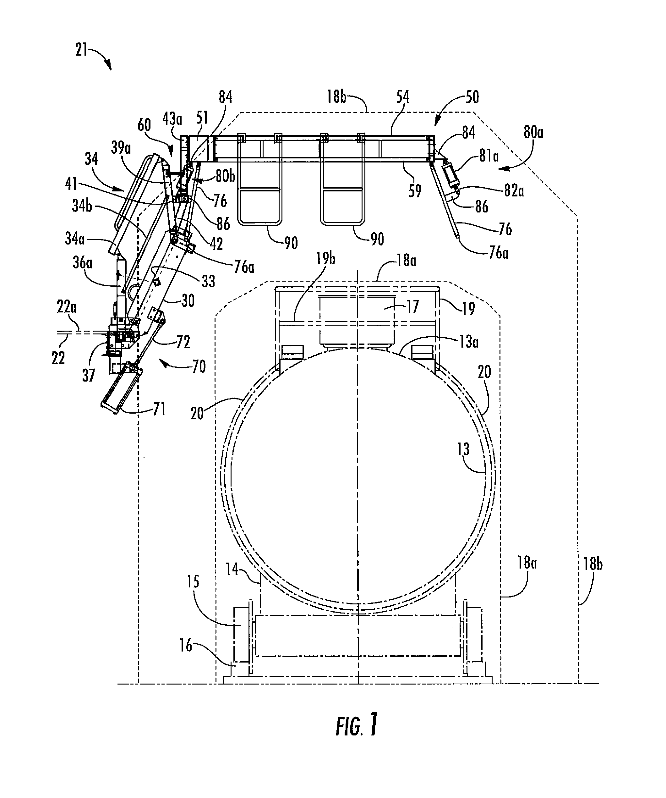
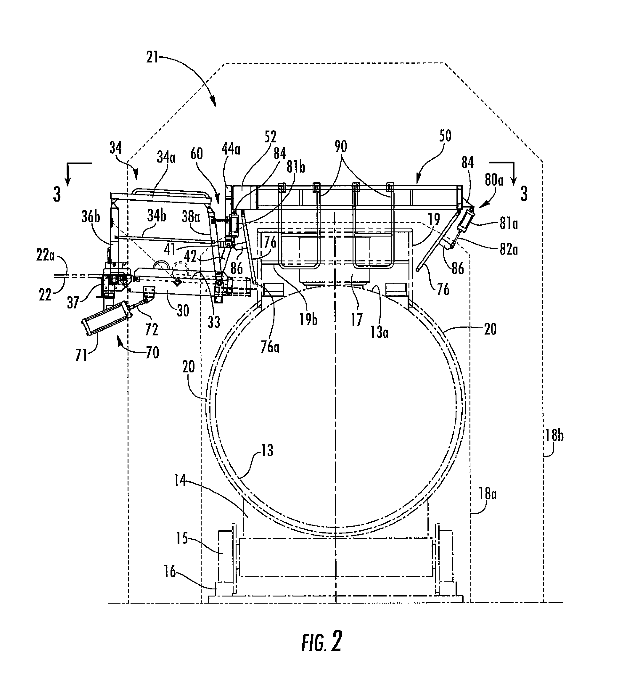
  • Fall protection cage with adjustable outboard upright
  • Fall protection cage with adjustable outboard upright
  • Fall protection cage with adjustable outboard upright

Examples


Embodiment Construction

[0026]Reference will now be made in detail to present embodiments of the invention, one or more examples of which are illustrated in the accompanying drawings. The detailed description uses numerical and letter designations to refer to features in the drawings. Like or similar designations in the drawings and description have been used to refer to like or similar parts of the invention.

[0027]Each example is provided by way of explanation of the invention, not limitation of the invention. In fact, it will be apparent to those skilled in the art that modifications and variations can be made in the present invention without departing from the scope or spirit thereof. For instance, features illustrated or described as part of one embodiment may be used on another embodiment to yield a still further embodiment. Thus, it is intended that the present invention covers such modifications and variations as come within the scope of the appended claims and their equivalents.

[0028]It is to be un...


PUM


Abstract

An apparatus that provides selectively deployable worker access with fall protection to at least a portion of the top of a container has a gangway that is configured to be retrofitted to an elevated platform from which the gangway and a fall protection cage is selectively deployable over the top of the container. The fall protection cage is connected to the gangway via a fixed stanchion and an abutment that is adjustably disposed outboard of the fixed stanchion and connected thereto via at least one selectively length adjustable screw member.

Description

CROSS-REFERENCE TO RELATED APPLICATIONS[0001]The present application claims priority to currently pending U.S. Provisional Patent Application Ser. No. 61 / 751,586, filed Jan. 11, 2013, which is hereby incorporated herein in its entirety for all purposes.STATEMENT REGARDING FEDERALLY SPONSORED RESEARCH OR DEVELOPMENT[0002]Not applicable.FIELD OF THE INVENTION[0003]The subject matter disclosed herein generally involves fall protection equipment for accessing the tops of rolling stock, and particularly extendable equipment that hangs from one end of an elevated loading platform.BACKGROUND OF THE INVENTION[0004]In accessing the tops of rolling stock (tank trucks, tank railroad cars, etc.), a gangway or bridge is used to allow workers to move cargo from an elevated loading platform to the top of the rolling stock. These gangways include cantilevers that usually carry a protective enclosure (aka cage) added to the outboard end to provide fall protection while the worker is on top of the ro...

Claims


Application Information

Patent Timeline
Patent Type & Authority Patents(United States)
IPC IPC(8): E01F1/00B65G69/26E01D19/10
CPCB65G69/22
Inventor THOMASSON, ALLYNTYNER, SANDY W.MACDONALD, ELLIE H.BENNETT, RONALD W.
Owner SAM CARBIS ASSET MANAGEMENT
Learn More