
Device and method for stacking fuel cell stack

a fuel cell and stacking technology, applied in the direction of layered products, electrochemical generators, chemistry apparatus and processes, etc., can solve the problems of deterioration of cell performance, leakage of reaction gas, crumpling and folding of thin mea, etc., to reduce leakage risk, efficient and accurate execution, and uniform stack performance

Active Publication Date: 2014-06-03
HYUNDAI MOTOR CO LTD
View PDF10 Cites 1 Cited by
  • Summary
  • Abstract
  • Description
  • Claims
  • Application Information

AI Technical Summary

Benefits of technology

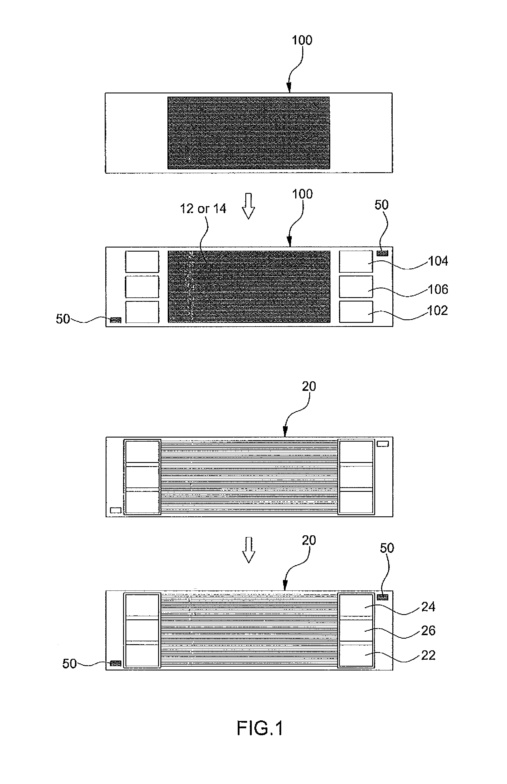
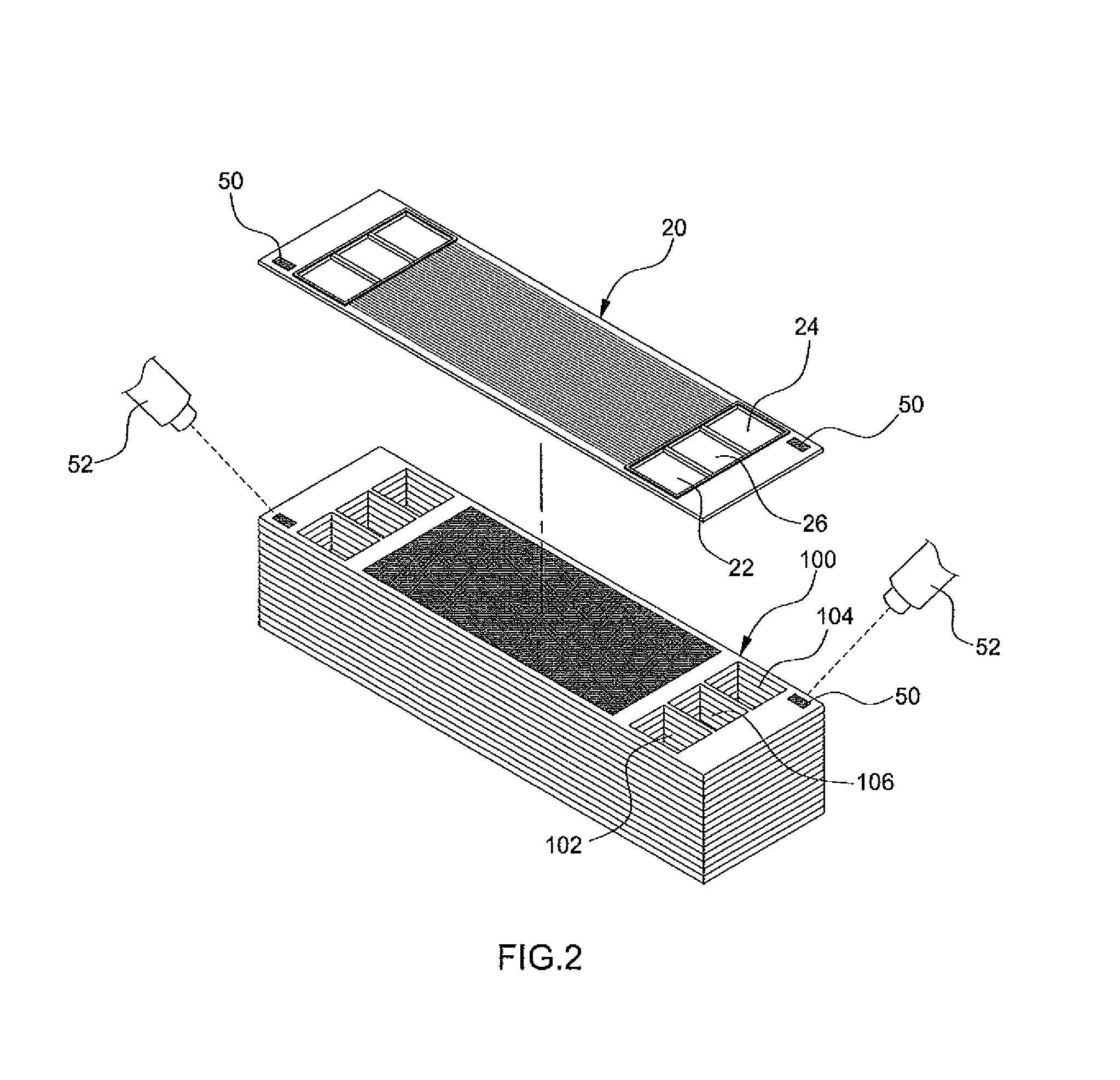
[0013]The present invention has been made in an effort to solve the above-described problems associated with prior art. Accordingly, the present invention provides a device and method for stacking a fuel cell stack, in which when a membrane-electrode assembly (MBA), a separation plate, etc., are automatically stacked in sequence by coating a phosphor at a predetermined position on each of the MEA, the separation plate, etc., the operation of sensing the phosphor in a phosphor sensor is automatically performed, so that the stacking of the MEA, the separation plate, etc., can be accurately executed.
[0019]Advantageously, when an MEA, a separation plate, etc. are automatically stacked in sequence by coating a phosphor at a predetermined position on each of the MEA, the separation plate, etc., the operation of sensing the phosphor in a phosphor sensor is automatically performed, so that the stacking of the MEA, the separation plate, etc., can be executed efficiently and accurately.
[0020]Particularly, as the MBA, the separation plate, etc. are accurately stacked together, the gas and coolant flow fields of the MEA and the gas and coolant manifolds of the separation plate precisely associated to correspond with each other, so that the airtightness by the gasket can be easily made and the flow fields are not blocked. Accordingly, it is possible to reduce the risk of leakage of the gas and coolant provided to the fuel cell stack and to implement uniform stack performance.

Problems solved by technology

If the stacking state of the fuel cell stack is not exactly determined, a leakage of reaction gas and deterioration of cell performance may result.
However, excessive guide lines may cause crumpling and folding of a thin MEA during the stacking of the MEA.

Method used


Image

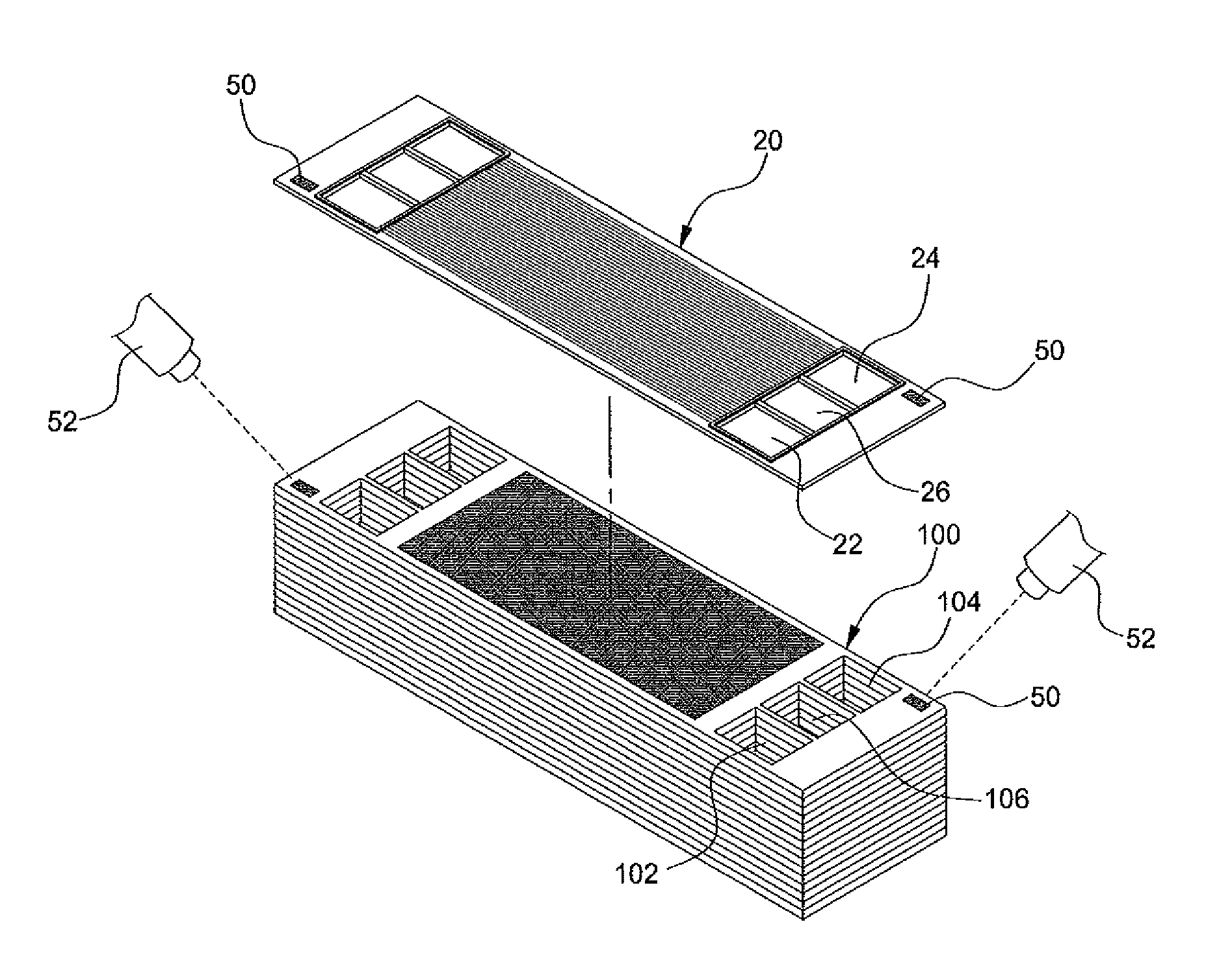
  • Device and method for stacking fuel cell stack
  • Device and method for stacking fuel cell stack
  • Device and method for stacking fuel cell stack

Examples


Embodiment Construction

[0027]Hereinafter reference will now be made in detail to various embodiments of the present invention, examples of which are illustrated in the accompanying drawings and described below. While the invention will be described in conjunction with exemplary embodiments, it will be understood that present description is not intended to limit the invention to those exemplary embodiments. On the contrary, the invention is intended to cover not only the exemplary embodiments, but also various alternatives, modifications, equivalents and, other embodiments, which may be included within the spirit and scope of the invention as defined by the appended claims.

[0028]The present invention relates to a device and method for stacking a fuel cell stack, which enables components such as a membrane-electrode assembly (MEA) and a separation plate to be exactly stacked when the fuel cell stack is assembled by stacking a few tens to a few hundreds of unit cells.

[0029]To this end, as shown in FIGS. 1 an...


PUM

PropertyMeasurementUnit
poweraaaaaaaaaa
electrical energyaaaaaaaaaa
unit cellaaaaaaaaaa

Abstract

Disclosed is a device and method for stacking a fuel cell stack, which enables automated accurate stacking of components constituting the fuel cell stack by using a phosphor coated thereon. Accordingly, when a membrane-electrode assembly (MEA), a separation plate, etc. are automatically stacked in sequence they are coated with phosphor at a predetermined position on each of the MEA, the separation plate, etc. A phosphor sensor is then positioned and configured to automatically determine whether or not the MEA and separator have been accurately stacked by detecting the presence of phosphor on the stacked MEA and separator plate respectively.

Description

CROSS-REFERENCE TO RELATED APPLICATION[0001]This application claims under 35 U.S.C. §119(a) the benefit of Korean Patent Application No, 10-2012-0091065 filed Aug. 21, 2012, the entire contents of which are incorporated herein by reference.BACKGROUND[0002](a) Technical Field[0003]The present invention relates to a device and method for stacking a fuel cell stack. More particularly, the present invention relates to a device and method for stacking a fuel cell stack, which enables the stacking state of components constituting the fuel cell stack to be accurately stacked using a phosphor.[0004](b) Background Art[0005]A fuel cell stack is a power generating device that generates electricity via an electrochemical reaction. Recently, fuel cells have been used to provide the main source of power to vehicles as part of the vehicles drive train. A fuel cell stack has a structure in which an anode to which hydrogen is supplied and a cathode to which air is supplied are stacked with a membran...

Claims


Application Information

Patent Timeline
Patent Type & Authority Patents(United States)
IPC IPC(8): H01M8/00
CPCH01M8/2465H01M8/242H01M8/0297Y02E60/50B32B37/02H01M8/04H01M8/24H01M8/04313H01M8/2483
Inventor BYUN, JUNG YEONCHOI, SUNG BUMLEE, JONG HYUN
Owner HYUNDAI MOTOR CO LTD
Learn More