
Multiple view transportation imaging systems

a transportation imaging and multi-view technology, applied in the direction of traffic movement detection, instruments, computing, etc., can solve the problems of inability to determine the speed, position or size of the vehicle in a linear manner, and the direct view of the front or rear portion of the vehicle may not be an optimal view for determining other vehicle characteristics, etc., to achieve less communication infrastructure, less installation and operation permit requirements, and low overhead power consumption

Active Publication Date: 2014-05-20
CONDUENT BUSINESS SERVICES LLC
View PDF16 Cites 2 Cited by
  • Summary
  • Abstract
  • Description
  • Claims
  • Application Information

AI Technical Summary

Benefits of technology

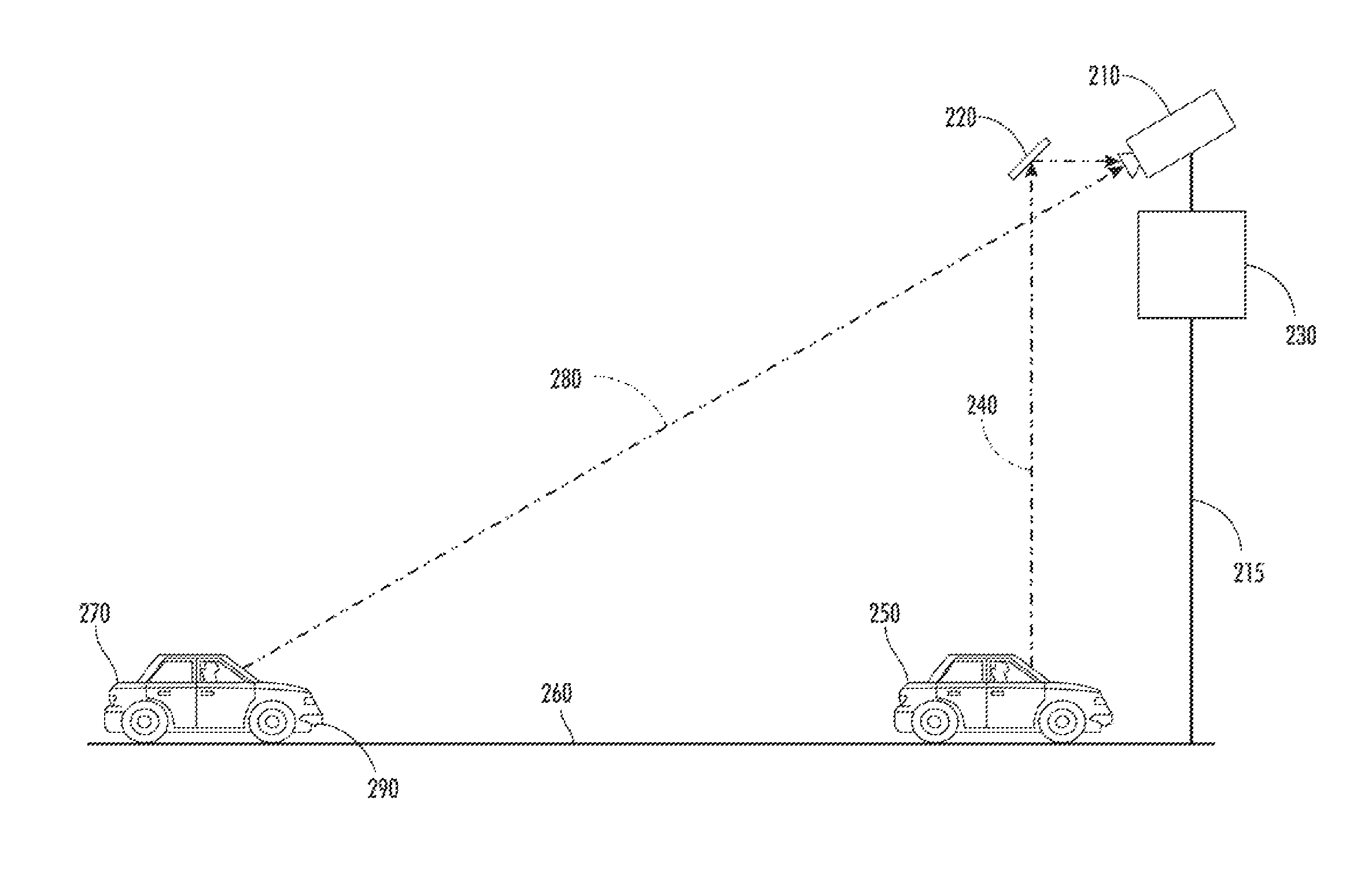
[0013]The present disclosure may be preferable over multiple-camera implementations by virtue of imposing lower overhead power consumption, less communication infrastructure, fewer installation and operation permit requirements, less maintenance, less space requirements, and looser or no synchronization requirements between cameras, among other benefits. Additionally, the present disclosure may effectively combine analytics from multiple views to produce more accurate results and may be less susceptible to view blocking.

Problems solved by technology

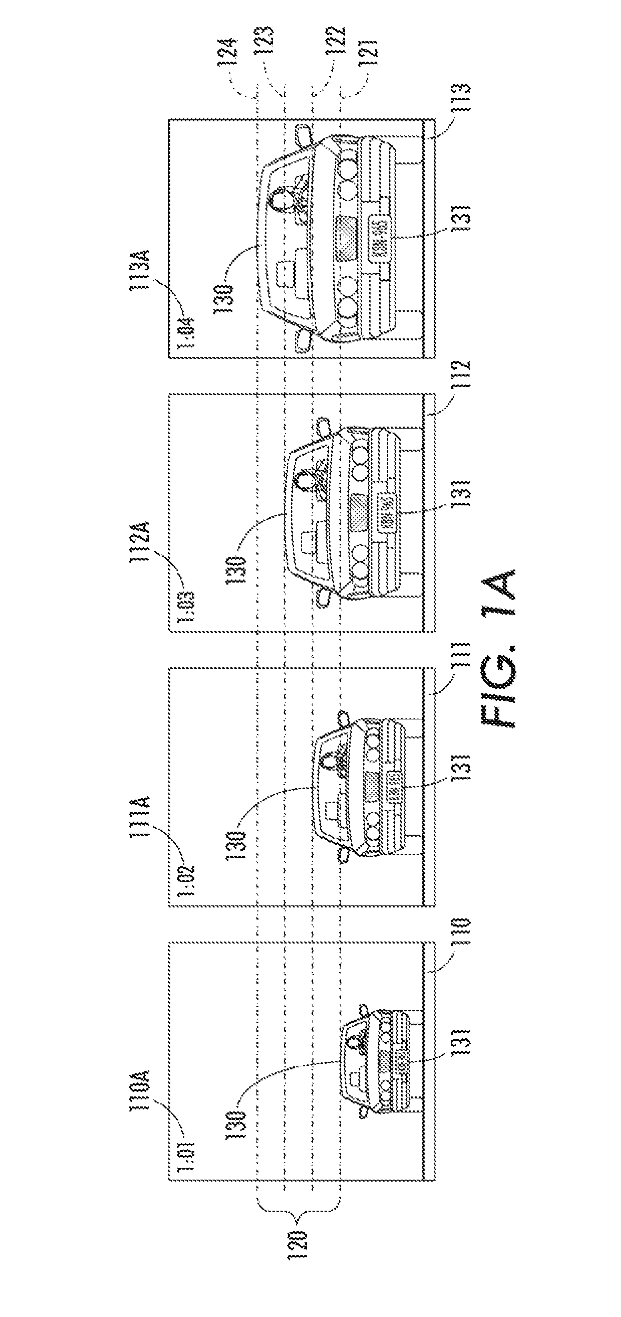
However, as described below, a direct view of the front or rear portion of a vehicle may not be an optimal view for determining other vehicle characteristics, such as vehicle speed.
However, even if vehicle 130 approaches the camera at a constant speed, such changes in position or size may not occur in a linear manner.
Thus, errors in identifying the same feature across multiple images may also affect the accuracy of speed determinations based thereon.
As a general matter, speed calculations based on rear or frontal views of a vehicle tend to be more susceptible to inaccuracy due to the limitations imposed by the geometric configuration than to errors in tracking vehicle features across images.
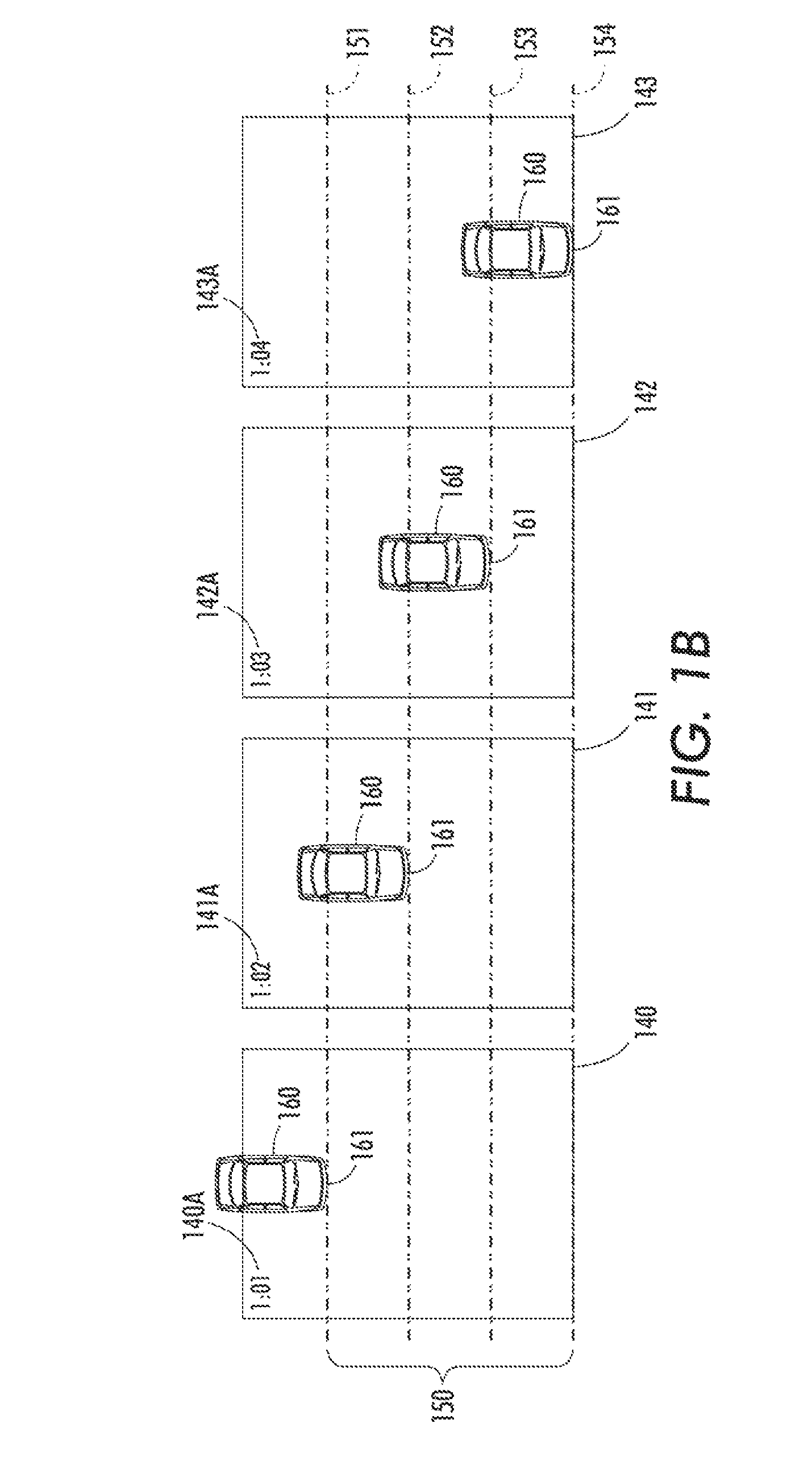
By contrast, speed calculations based on top-down views of a vehicle tend to be less susceptible to inaccuracy due to the particular geometric configuration being used but more susceptible to errors in tracking vehicle features due to height variations between different vehicles.
By contrast, the accuracy of speed calculations may be more susceptible to errors in tracking the same feature of vehicle 160 across different images due to height variations between different vehicles.
Similar issues may arise when analyzing sequential images taken of the side portion of a vehicle, which may further be complicated by potential occlusion by the presence of other vehicles.
However, such multi-camera systems may impose higher overhead costs due to increased power consumption, increased complexity due to a potential need for temporal and spatial alignment of the imagery, increased communication infrastructure, the need for additional installation and operation permits, and maintenance, among other costs.

Method used


Image

  • Multiple view transportation imaging systems
  • Multiple view transportation imaging systems
  • Multiple view transportation imaging systems

Examples


Embodiment Construction

[0031]The following detailed description refers to the accompanying drawings. Wherever possible, the same reference numbers are used in the drawings and the following description to refer to the same or similar parts. While several exemplary embodiments and features of the present disclosure are described herein, modifications, adaptations, and other implementations are possible, without departing from the spirit and scope of the present disclosure. Accordingly, the following detailed description does not limit the present disclosure. Instead, the proper scope of the disclosure is defined by the appended claims.

[0032]In the description and claims, unless otherwise specified, the following terms may have the following definitions.

[0033]A view may refer to an optical path of a camera's field of view. For example, a direct view may refer to a camera receiving light rays from an object that it is recording such that the light rays travel from the object to the camera structure in an ess...


PUM


Abstract

A camera may be positioned to have a direct view of on-coming vehicle traffic from a first perspective. Additionally, a reflective surface, such as a mirror, may be positioned within the viewing area of the same camera to provide the camera with a reflected view of vehicle traffic from a second perspective. The images recorded by the camera may then be received by a computing device. The computing device may separate the images into a direct view region and a reflected view region. After separation, the regions may be analyzed independently and / or combined with other regions, and the analyzed data may be stored. The regions may be analyzed to determine various vehicle characteristics, including, but not limited to, vehicle speed, license plate identification, vehicle occupancy, vehicle count, and vehicle type.

Description

TECHNICAL FIELD[0001]The present disclosure relates generally to methods, systems, and computer-readable media for monitoring objects, such as vehicles in traffic, from multiple, different optical perspectives using a single-camera architecture.BACKGROUND[0002]Traffic cameras are frequently used to assist law enforcement personnel in enforcing traffic laws and regulations. For example, traffic cameras may be positioned to record passing traffic, and the recordings may be analyzed to determine various vehicle characteristics, including vehicle speed, passenger configuration, and other characteristics relevant to traffic rules. Typically, in addition to detecting characteristics related to compliance with traffic rules, traffic cameras are also tasked with recording and analyzing license plates in order to associate detected characteristics with specific vehicles or drivers.[0003]However, law enforcement transportation cameras are often positioned with a view that is suboptimal for mu...

Claims


Application Information

Patent Timeline
Patent Type & Authority Patents(United States)
IPC IPC(8): G06K9/00
CPCG08G1/04G08G1/017
Inventor SHIN, HELEN HAEKYUNGLOCE, ROBERT P.WU, WENCHENGWADE, THOMAS F.PAUL, PETERBERNAL, EDGAR
Owner CONDUENT BUSINESS SERVICES LLC
Learn More