Eureka AIR delivers breakthrough ideas for toughest innovation challenges, trusted by R&D personnel around the world.

Display device of work vehicle

a technology of work vehicle and display device, which is applied in the field of display device, can solve the problem of unfavorable smooth operation of the attachment by the operating member, and achieve the effect of smooth operation by the operating member

Active Publication Date: 2014-05-20
KUBOTA LTD
View PDF12 Cites 0 Cited by
  • Summary
  • Abstract
  • Description
  • Claims
  • Application Information

AI Technical Summary

Benefits of technology

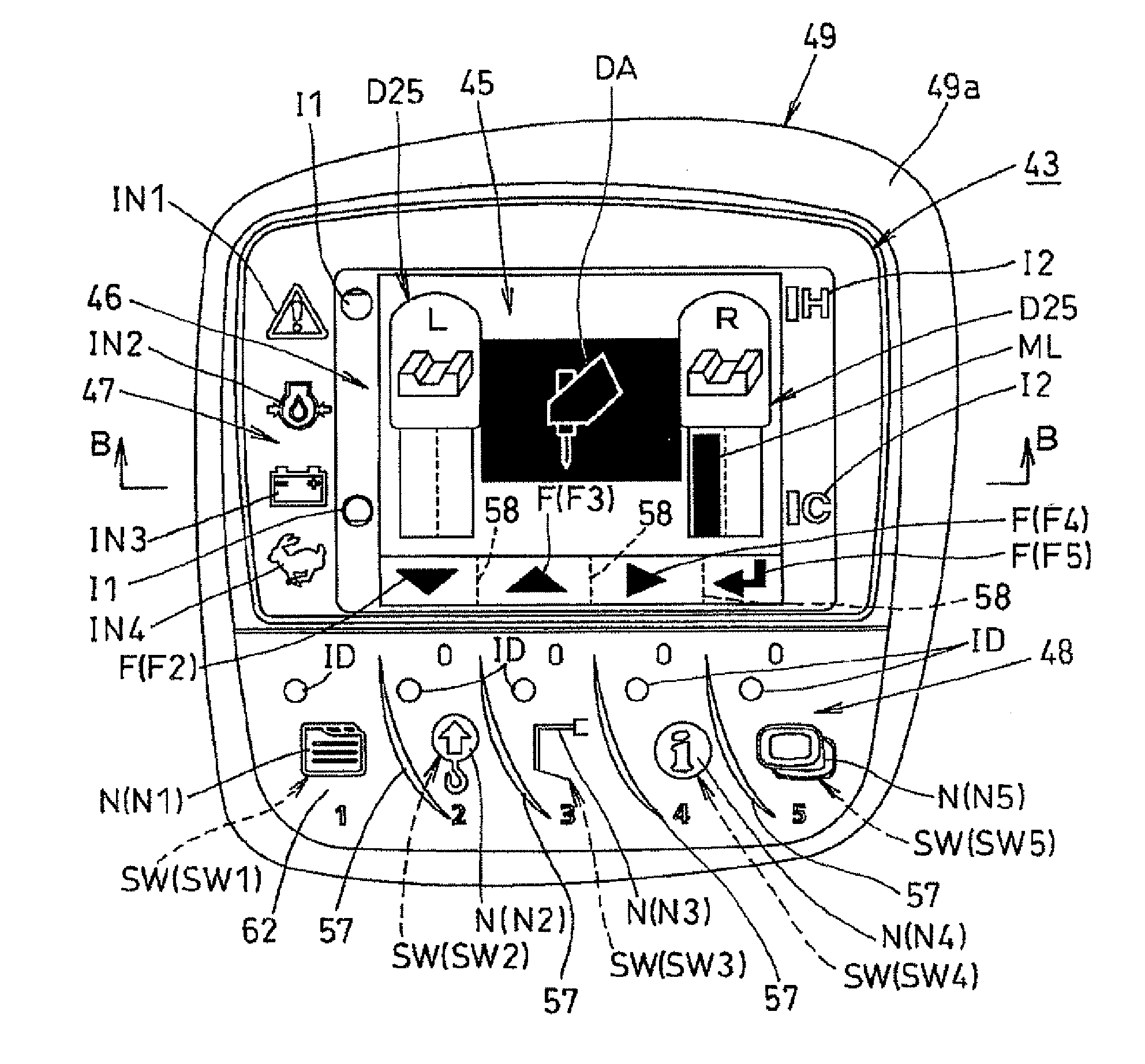
The invention allows the display to show the maximum flow rate of hydraulic oil that can be achieved when using a certain operating member. This makes it easy to operate the actuator and ensures smooth operation.

Problems solved by technology

In the case of the prior art, however, it is sometimes difficult to correlate the maximum flow rate level displayed in the display unit with a particular operating member, thereby making it impossible to smoothly operate the attachment by the operating member.

Method used


Image

  • Display device of work vehicle
  • Display device of work vehicle
  • Display device of work vehicle

Examples


Embodiment Construction

[0037]An embodiment of the present invention is described hereinbelow with reference to the drawings. FIGS. 1 to 22 show an embodiment of the present invention.

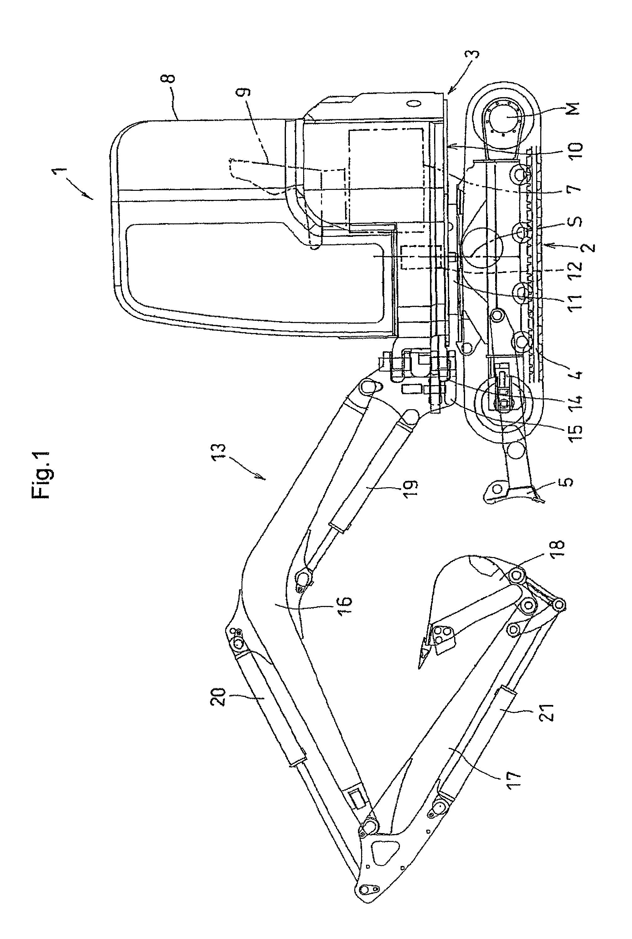
[0038]In FIG. 1, a work vehicle (backhoe) 1 is configured from a bottom travel apparatus 2 and a top swiveling body 3.

[0039]The travel apparatus 2 comprises a pair of left and right travel members 4 having rubber track belts, and a crawler-type travel apparatus in which the travel members 4 are driven by a travel motor M is used as the travel apparatus 2. A dozer 5 is provided at the front of the travel apparatus 2.

[0040]The swiveling body 3 has a swivel 10 supported on the travel apparatus 2 so as to be capable of swiveling left and right around a vertical swivel shaft via a swivel bearing 11, and also has a work apparatus 13 (excavating apparatus) provided at the front of the swivel 10; and the swivel 10 is configured so as to be swiveled around a swivel center S by a swivel motor 12. An engine 7, a driver seat 9, a fuel ta...


PUM


Abstract

A display device for a work vehicle having a work apparatus operated by an actuator, the device comprising:a flow rate limit setting unit for variably setting a maximum flow rate level of hydraulic oil supplied to and drained from the actuator by operating an operating member; anda display unit for displaying the maximum flow rate level of the hydraulic oil supplied to and drained from the actuator;wherein the hydraulic oil whose flow rate corresponds to a manipulated variable of the operating member is supplied to and drained from the actuator within a range defined by the maximum flow rate level that is set by the flow rate limit setting unit to cause the work apparatus to operate, with an operating member symbol for indicating the operating member being displayed in the display unit; andthe maximum flow rate level of the hydraulic oil supplied to and drained from the actuator by operating the operating member is displayed in accordance with the operating member symbol.

Description

BACKGROUND OF THE INVENTION[0001]1. Field of the Invention[0002]The present invention relates to display device for a backhoe or another work vehicle.[0003]2. Description of the Related Art[0004]Conventional backhoes and other work vehicles include those that have an attachment (attachment tool) operated by an actuator, and are provided with flow rate limit setting means for variably setting the maximum flow rate level of hydraulic oil supplied to and drained from the actuator by the operation of an operating member. The hydraulic oil whose flow rate corresponds to the manipulated variable of the operating member is supplied to and drained from the actuator within a range defined by the maximum flow rate level that has been set by the flow rate limit setting means to cause the attachment to operate (e.g., JP2007-92763A).[0005]Backhoes and other work vehicle also include those in which an instrument panel or other display unit is provided in the vicinity of the driver seat (e.g., JP2...

Claims


Application Information

Patent Timeline
Patent Type & Authority Patents(United States)
IPC IPC(8): G08B3/00B60K35/10
CPCE02F3/963E02F9/26E02F9/20B60K35/10
Inventor MIURA, KEISUKEUEDA, MASAAKI
Owner KUBOTA LTD
Why Eureka
Eureka Blog
Learn More