
Collapsible portable shelter

a portable shelter and collapsible technology, applied in tents/canopies, building types, constructions, etc., can solve the problems of easy dislocation and carrying of umbrellas, and the location of the roof portion very close, so as to achieve the effect of wide rang

Inactive Publication Date: 2014-05-13
NICHOLS JOHN ALEXANDER
View PDF15 Cites 17 Cited by
  • Summary
  • Abstract
  • Description
  • Claims
  • Application Information

AI Technical Summary

Benefits of technology

The present invention provides a collapsible portable shelter that can be easily collapsed and erected. The shelter includes a panel made of flexible material that is connected to a first and second strut. The struts are resiliently flexible and can be adjusted to resist lateral movement. The shelter can be secured to a surface by an anchoring member, which can be adjusted by re-positioning the ballast member. The panel can be oriented in different directions by adjusting the ballast member. The shelter also includes a brace element for coupling with the struts. The brace element can be adjusted to tension the panel. The shelter can be stored in a collapsed form and includes a portable container for this purpose. The technical effects of the invention include improved portability, flexibility, and ease of use of the collapsible portable shelter.

Problems solved by technology

A difficulty with such umbrellas relates to the requirement that they must be oriented to minimise their resistance to the prevailing wind and to prevent them from being carried away with the wind while at the same time providing adequate protection from the sun.
In addition unless properly fixed in the ground, such umbrellas can readily become dislodged and carried away as a result of strong winds which create a potential danger to other users of the beach.
A difficulty with such shelters is that the roof portion is located very close to the ground.
They must also be oriented appropriately to accommodate for the prevailing wind conditions which in many cases are not conducive to providing adequate shelter from the sun.

Method used


Image

  • Collapsible portable shelter
  • Collapsible portable shelter
  • Collapsible portable shelter

Examples


first embodiment

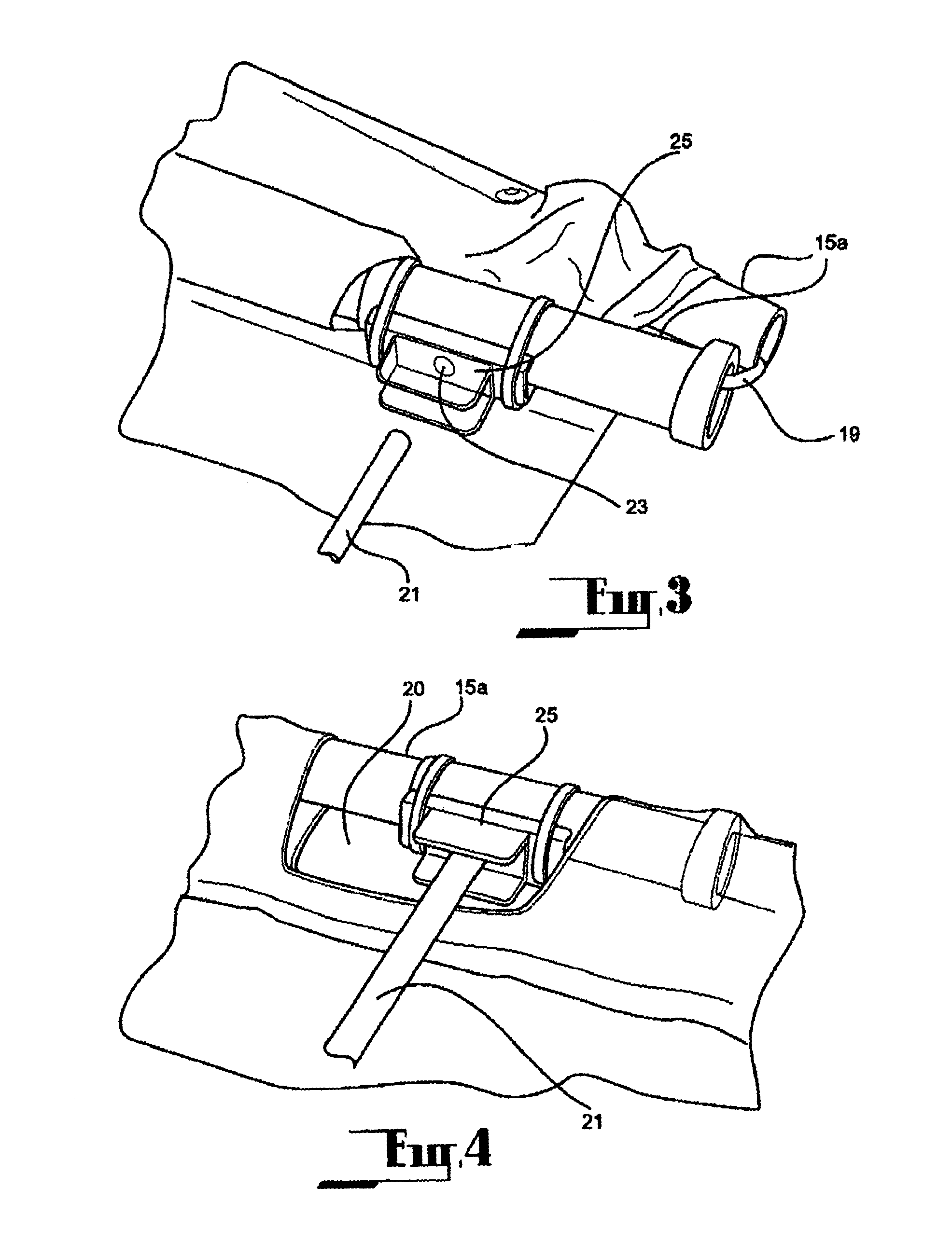
[0059]FIGS. 1 to 6 illustrate a collapsible portable shelter 2 in various states according to the present invention.

[0060]FIG. 1 shows the shelter 2 collapsed completely into a bundle 11 which can be inserted into a portable container 13, such as a carry bag. When it is desired to erect the shelter 2, the bundle 11 is extracted from the carry bag 13 and the panel 17 of the shelter 2 is unrolled as shown in FIG. 2. The panel 17 can then be unfolded to begin erecting the shelter 2.

[0061]The shelter 2 of the first embodiment comprises at least a first strut 15 and a second strut 15, each strut 15 being resiliently flexible. It should be noted that further struts can be provided to enhance the strength and / or stability of the shelter 2. The shelter 2 further comprises a panel 17 formed of a flexible material, such as a suitable fabric material. Preferably, the material is substantially opaque to sunlight. Alternatively, or additionally, the material is substantially capable of blocking ...


PUM


Abstract

A collapsible portable shelter including at least a first strut and a second strut, each strut being resiliently flexible, a panel formed of a flexible material coupled with the first strut and the second strut, and an anchoring member for anchoring the panel relative to a surface. The first strut is received along a first side of the panel and the second strut is received along a second side of the panel, the second side opposing the first side. The first strut and the second strut each has a portion extending beyond a third side of the panel. A portion of each of the first strut and second strut is to be received in the surface to resist lateral movement of said part received in the ground. The orientation of the panel with respect to the surface can be readily varied by adjusting the anchoring.

Description

CROSS-REFERENCE TO RELATED APPLICATION[0001]This application is the U.S. national phase of PCT Appln. No. PCT / AU2010 / 001422 filed on Oct. 25, 2012, which claims priority to AU Patent Application No. 2009905179 filed on Oct. 23, 2009 the disclosures of which are incorporated in their entirety by reference herein.FIELD OF THE INVENTION[0002]This invention relates to a collapsible portable shelter.BACKGROUND[0003]The following discussion of the background art is intended to facilitate an understanding of the present invention only. It should be appreciated that the discussion is not an acknowledgement or admission that any of the material referred to was published, known or part of the common general knowledge of the person skilled in the art in any jurisdiction as at the priority date of the invention.[0004]The invention relates to a shelter which, for example, can be used on the beach or the like in order to protect the user from exposure to the sun. One existing form of shelter comp...

Claims


Application Information

Patent Timeline
Patent Type & Authority Patents(United States)
IPC IPC(8): E04H15/58E04H15/62
CPCE04H15/58E04H15/63E04H15/005E04H15/44E04H15/64
Inventor NICHOLS, JOHN ALEXANDER
Owner NICHOLS JOHN ALEXANDER
Learn More