
Communication control device, communication control method, and program

a communication control and communication control technology, applied in the execution of user interfaces, static indicating devices, instruments, etc., can solve the problems of user's operation complicated, user may not enjoy sufficient convenience, and the user cannot perform intuitive manipulation, etc., to achieve accurate recognition of the position of the communication devi

Inactive Publication Date: 2014-05-06
SONY CORP
View PDF7 Cites 1 Cited by
  • Summary
  • Abstract
  • Description
  • Claims
  • Application Information

AI Technical Summary

Benefits of technology

[0006]In general, when data is exchanged between the above-described communication devices, the user designates desired transmission data and a device of a communication partner on a screen of any one of a transmission source and a transmission destination, and issues a data transmission command. As a method of issuing the data transmission command, there are various types such as an icon dragging, menu selection, a text-based command input, and the like. However, the user should know an address, an identification name, or an icon representing the communication partner device in any method. This makes user's operation complicated and prevents the user from performing an intuitive manipulation. “Pick and Drop” disclosed in the above-described Japanese Patent Laid-Open Publication No. 2001-142825 is a method directed to a data exchange between devices with an intuitive user interface. However, since a special interface should be prepared in the devices of both the transmission source and the transmission destination for the “Pick and Drop” method, the user may not enjoy sufficient convenience.
[0007]Meanwhile, the above-described environment map enables a computer to accurately recognize a position of a communication device located in a real space. Thus, it is expected that a data transmission instruction can be more intuitively provided between devices by a user interface to which the environment map is applied.

Problems solved by technology

This makes user's operation complicated and prevents the user from performing an intuitive manipulation.
However, since a special interface should be prepared in the devices of both the transmission source and the transmission destination for the “Pick and Drop” method, the user may not enjoy sufficient convenience.

Method used


Image

  • Communication control device, communication control method, and program
  • Communication control device, communication control method, and program
  • Communication control device, communication control method, and program

Examples


Embodiment Construction

)

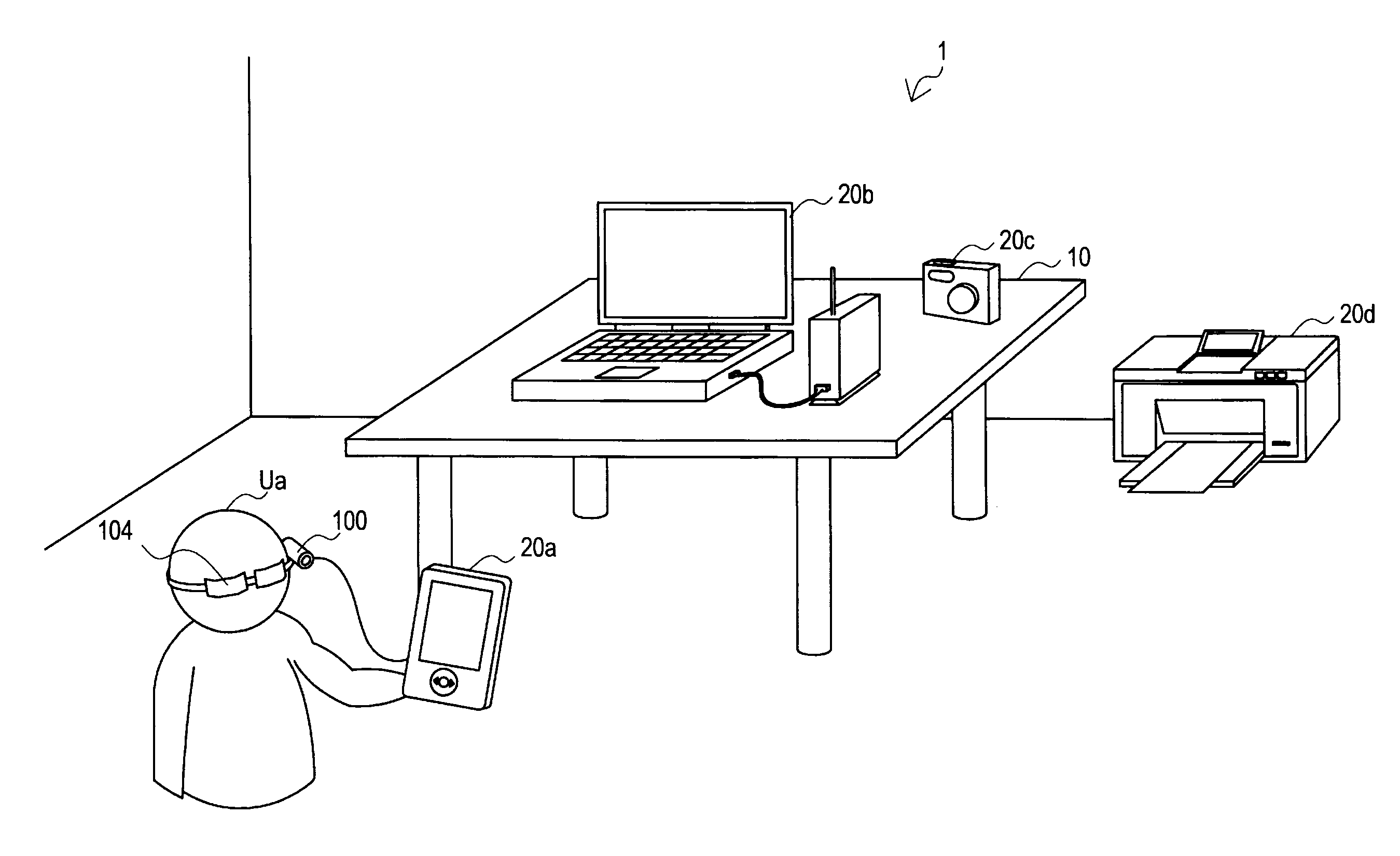
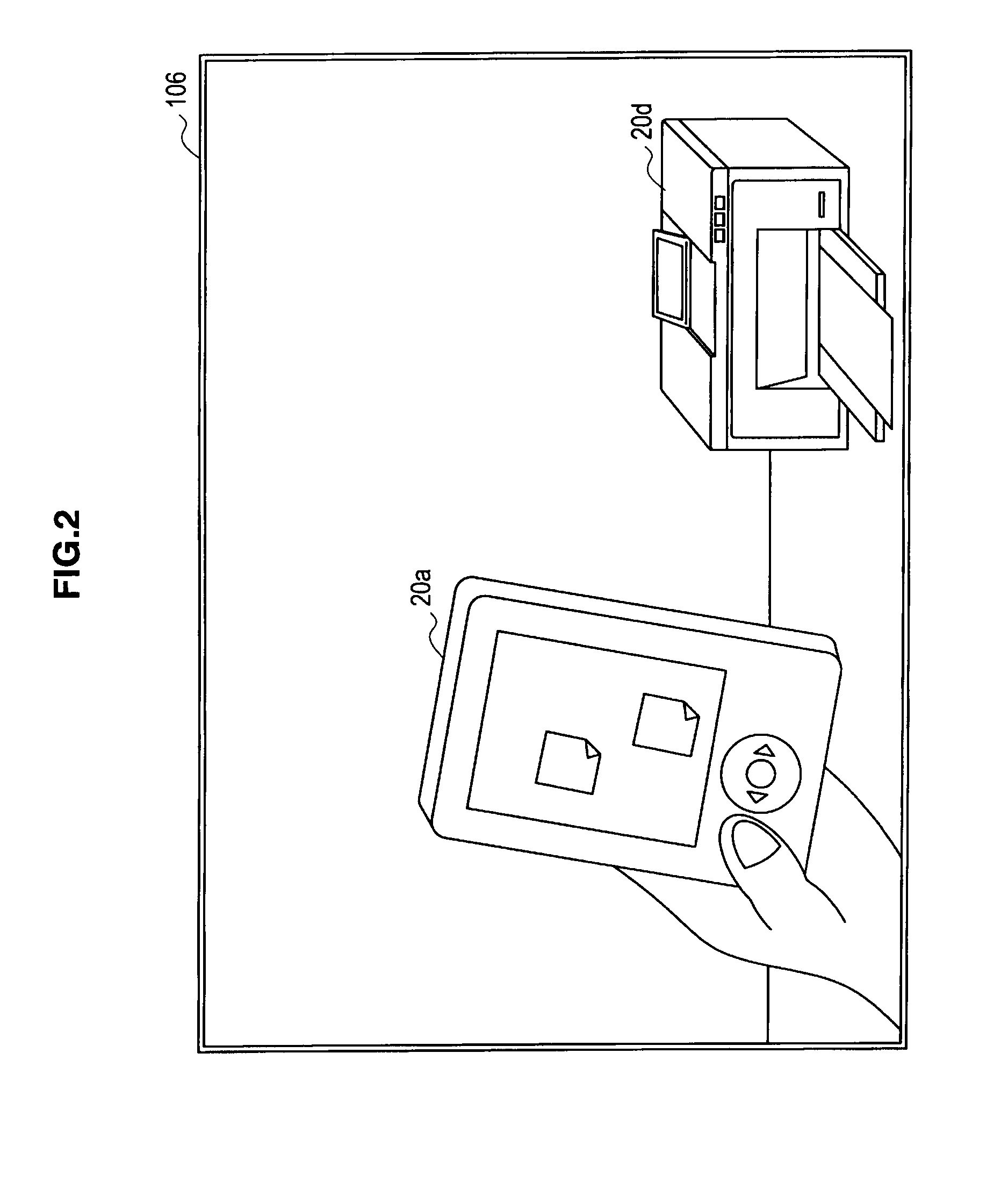
[0041]Hereinafter, preferred embodiments of the present invention will be described in detail with reference to the appended drawings. Note that, in this specification and the appended drawings, structural elements that have substantially the same function and structure are denoted with the same reference numerals, and repeated explanation of these structural elements is omitted.

[0042]The “detailed description of the embodiment(s)” will be given in the following order.

[0043]1. Overview of System

[0044]2. Configuration of Communication Device according to Embodiment

[0045]3. Configuration of Communication Control Device according to Embodiment[0046]3-1. Imaging Unit[0047]3-2. Environment Map Generating Unit[0048]3-3. Communication Processing Unit[0049]3-4. Display Control Unit[0050]3-5. Flow of Communication Control Process

[0051]4. Modified Examples

[0052]5. Summary

[0053]First, the overview of the system according to an embodiment of the present invention will be described with referen...


PUM


Abstract

There is provided a communication control device including: a data storage unit storing feature data representing features of appearances of one or more communication devices; an environment map building unit for building an environment map representing positions of communication devices present in a real space based on an input image obtained by imaging the real space and the feature data stored in the data storage unit; a detecting unit for detecting a user input toward a first communication device designating any data provided in the first communication device and a direction; a selecting unit for selecting a second communication device serving as a transmission destination of the designated data from the environment map based on the direction designated by the user input; and a communication control unit for transmitting the data provided in the first communication device from the first communication device to the second communication device.

Description

BACKGROUND OF THE INVENTION[0001]1. Field of the Invention[0002]The present invention relates to a communication control device, a communication control method, and a program.[0003]2. Description of the Related Art[0004]Recently, technology called augmented reality (AR), which processes an image obtained by imaging a real space and presents the processed image to a user, has been receiving attention. In the AR technology, it is important that a computer recognize a situation of the real space. For example, as technology for recognizing the situation of the real space, Japanese Patent Laid-Open Publication No. 2008-304268 discloses a method of dynamically generating an environment map representing three-dimensional positions of physical objects present in the real space by applying technology called simultaneous localization and mapping (SLAM) capable of simultaneously estimating a position and a posture of a camera and positions of feature points present in an image of the camera. A...

Claims


Application Information

Patent Timeline
Patent Type & Authority Patents(United States)
IPC IPC(8): G06T17/00G06T13/00G06T19/00G06F3/048G06F3/0481G06F3/0486
CPCG06F3/017G06F3/14G09G2370/025G09G2370/04G06F9/451G06F3/1423G06F3/1454G06F13/38G06F13/385
Inventor MATSUDA, KOUICHI
Owner SONY CORP
Learn More