
Pneumatic tire with tread having rib portion, sub-grooves and sipes

a technology of pneumatic tires and treads, which is applied in the direction of non-skid devices, vehicle components, transportation and packaging, etc., can solve the problems of difficult to achieve both the driving stability on a wet road surface and the snow performance by using these tread patterns, so as to improve the driving stability of pneumatic tires, avoid the decrease in the rigidity and avoid the effect of the first land portion's rigidity

Inactive Publication Date: 2014-05-06
THE YOKOHAMA RUBBER CO LTD
View PDF19 Cites 2 Cited by
  • Summary
  • Abstract
  • Description
  • Claims
  • Application Information

AI Technical Summary

Benefits of technology

The present invention improves the rigidity and drainage of the tire's first land portion and ensures better snow performance and driving stability on a wet road surface. This is achieved by specifying the locations of the main grooves and forming sub-grooves with a curved shape in the edge portions of the first land portion. Additionally, a rib portion is formed in the area of the first land portion on the tire equator line. The invention also includes the installation of sipes between the sub-grooves and the main grooves, as well as the arrangement of second and third land portions with a predetermined width and rib structure. Furthermore, fine grooves and see-through portions are provided to further improve the driving stability and snow performance.

Problems solved by technology

However, it is still difficult to achieve both the driving stability on a wet road surface and the snow performance by using these tread patterns.Patent Document 1: Japanese patent application Kokai publication No.

Method used


Image

  • Pneumatic tire with tread having rib portion, sub-grooves and sipes
  • Pneumatic tire with tread having rib portion, sub-grooves and sipes

Examples


examples

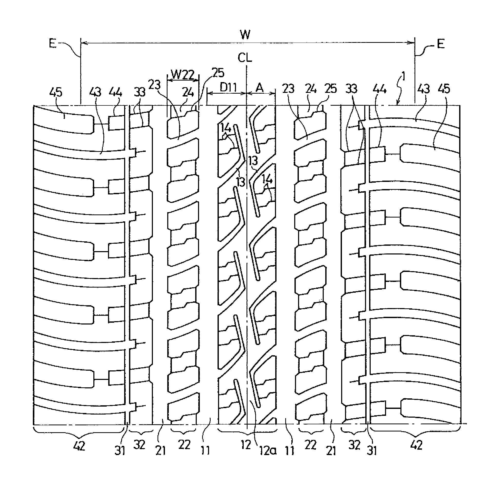
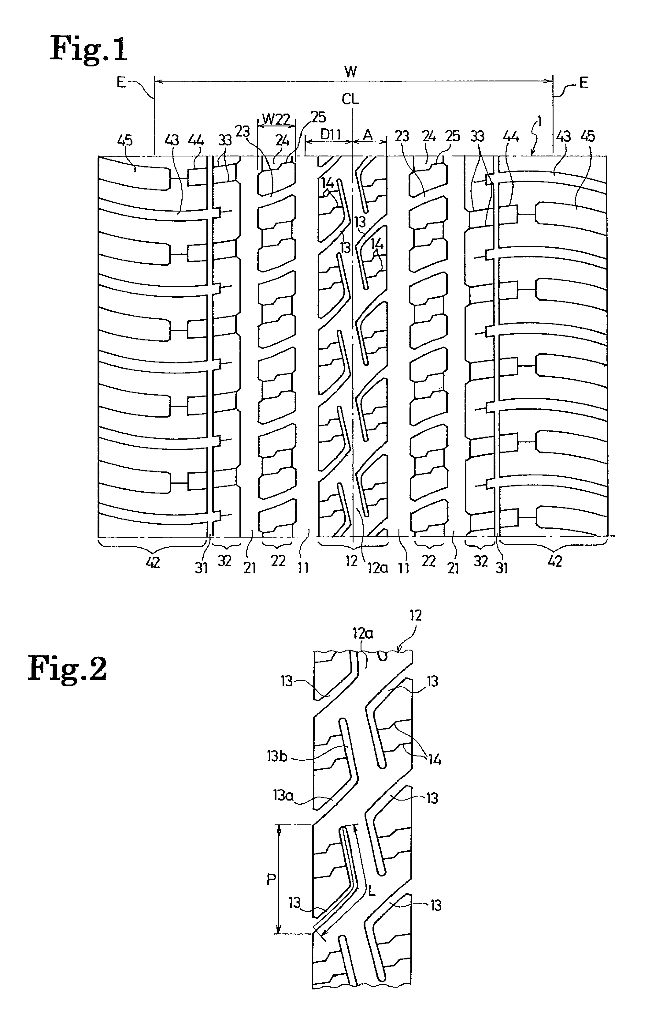
[0040]Pneumatic tires according to each of Examples 1 to 5 were made with a tire size of P265 / 70R17 113H (TRA), and with the tread pattern shown in FIG. 1, but by setting a ratio of the distance between the center position of each first main groove and the tire equator line to the ground contact width W (hereinafter referred to as a “location of first main groove”) as well as a ratio (L / P) of the length L of the center line of each sub-groove to the pitch length P of the sub-grooves in the tire circumferential direction as shown in Table 1.

[0041]Tires according to each of Comparative Examples 1 to 3 were prepared for the comparison purpose. The tires according to Comparative Example 1 had no sub-grooves. The tires according to Comparative Example 2 had sub-grooves, the two ends of each of which were opened to the two main grooves situated at the two sides of the first land portion, respectively. The tires according to Comparative Example 3 had the ratio (L / P) of the length L of the ...


PUM


Abstract

A pneumatic tire is configured such that: paired first main grooves extending in a tire circumferential direction are provided on the two sides of a tire equator line in a tread portion, respectively; a distance between a center position of each first main groove and the tire equator line is set at 8% to 20% of a ground contact width W; a first land portion is defined between these first main grooves; multiple sub-grooves each having a curved shape are formed in each of both edge portions of the first land portion at intervals in the tire circumferential direction; one end of each sub-groove is opened to the corresponding first main groove, and the other end of the sub-groove is terminated inside the first land portion; a rib portion continuously extending in the tire circumferential direction is formed in an area of the first land portion on the tire equator line; and a relation between a length (L) of a center line of each sub-groove and a pitch length (P) of the sub-grooves in the tire circumferential direction satisfies 1.1×P≦L≦2.0×P.

Description

TECHNICAL FIELD[0001]The present invention relates to an all-season or mud & snow pneumatic tire, and more specifically to a pneumatic tire: which is improved in the driving stability on a wet road surface; and which is capable of ensuring a better snow performance.BACKGROUND ART[0002]For improving the driving stability of a pneumatic tire on a wet road surface, enhancement of the edge effect is effective, and the ensuring of the block rigidity is also important at the same time. Meanwhile, one of the significant factors for ensuring the snow traction is increase in a volume of grooves. For instance, in a case where the volume of grooves in the tread portion of the pneumatic tire is increased, the snow traction can be improved, whereas the block rigidity is decreased, so that the driving stability on a wet road surface is deteriorated. As described above, the conditions for improving the driving stability on a wet road surface and the snow performance are in a trade-off relationship...

Claims


Application Information

Patent Timeline
Patent Type & Authority Patents(United States)
IPC IPC(8): B60C11/12B60C11/03
CPCB60C2011/0388B60C2011/1213B60C11/12B60C2011/0381B60C11/0306
Inventor EBIKO, MASAHIRO
Owner THE YOKOHAMA RUBBER CO LTD
Learn More