
Printer for minimizing adverse mixing of high and low luminance inks at nozzle face of inkjet printhead

a printing machine and inkjet printing technology, applied in the field of inkjet printing, can solve the problems of adversely affecting print quality, affecting the maintenance routine of printheads, and adding to the complexity of other known pagewidth printing systems, and achieve the effect of minimizing adverse color mixing and high luminance ink

Active Publication Date: 2014-04-22
MEMJET TECH LTD
View PDF5 Cites 0 Cited by
  • Summary
  • Abstract
  • Description
  • Claims
  • Application Information

AI Technical Summary

Benefits of technology

The patent describes an inkjet printhead and ink set that can minimize color mixing. The printhead has nozzle plates made of ceramic materials, which are often wetting and can cause color mixing. The invention suggests using a surfactant in the ink to improve color mixing. The ink set includes a plurality of aqueous inks with different luminance colors, and the amount of surfactant in the high luminance ink is at least 0.4 wt% greater than in the low luminance ink. The ink vehicles include ethylene glycol, 2-pyrrolidinone, and glycerol, among others. Overall, the invention aims to improve the color accuracy and quality of inkjet printing.

Problems solved by technology

By contrast, widely spaced color planes necessitate complex media feed mechanisms to achieve proper alignment, adding to the complexity of other known pagewidth printing systems (e.g. HP Edgeline).
This close spacing of color planes produces problems which are unique to such printheads.
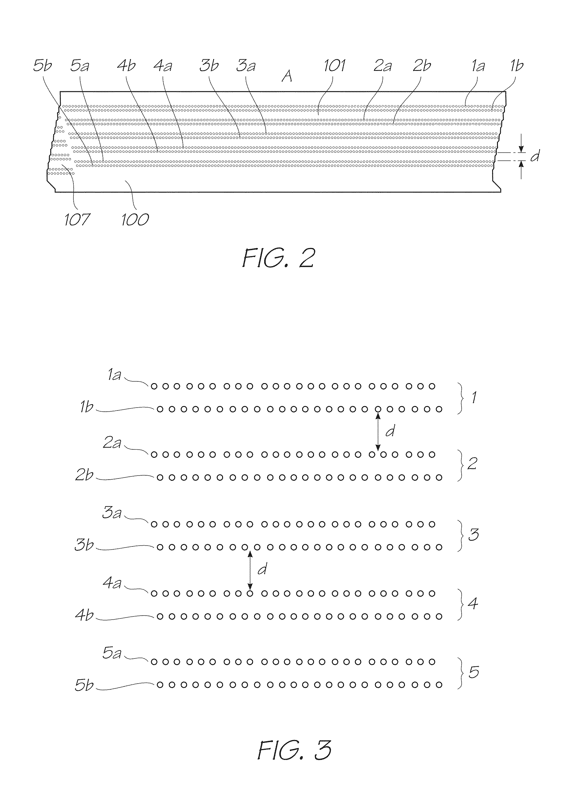
A significant problem of closely spaced nozzle rows from different color planes is one of color mixing on the nozzle plate of the printheads.
If, for example, black ink mixes into a yellow ink on the nozzle plate, then this may adversely affect print quality as well as impacting on printhead maintenance routines.
However, such coatings add to the cost and complexity of printhead fabrication.
Moreover, they do not control a direction of color mixing so as to favor acceptable color mixing over adverse color mixing.

Method used


Image

  • Printer for minimizing adverse mixing of high and low luminance inks at nozzle face of inkjet printhead
  • Printer for minimizing adverse mixing of high and low luminance inks at nozzle face of inkjet printhead
  • Printer for minimizing adverse mixing of high and low luminance inks at nozzle face of inkjet printhead

Examples


Embodiment Construction

[0070]The present invention is particularly suitable for use with the Applicant's Memjet® printheads, which comprise closely spaced color planes on a single printhead. As foreshadowed above, such printheads are more prone to adverse color mixing the nozzle face than other prior art printheads. However, it will be appreciated that the present invention is suitable for use in any printhead where it is desirable to avoid adverse color mixing between different color planes on the nozzle face.

Pagewidth Printhead and Printer

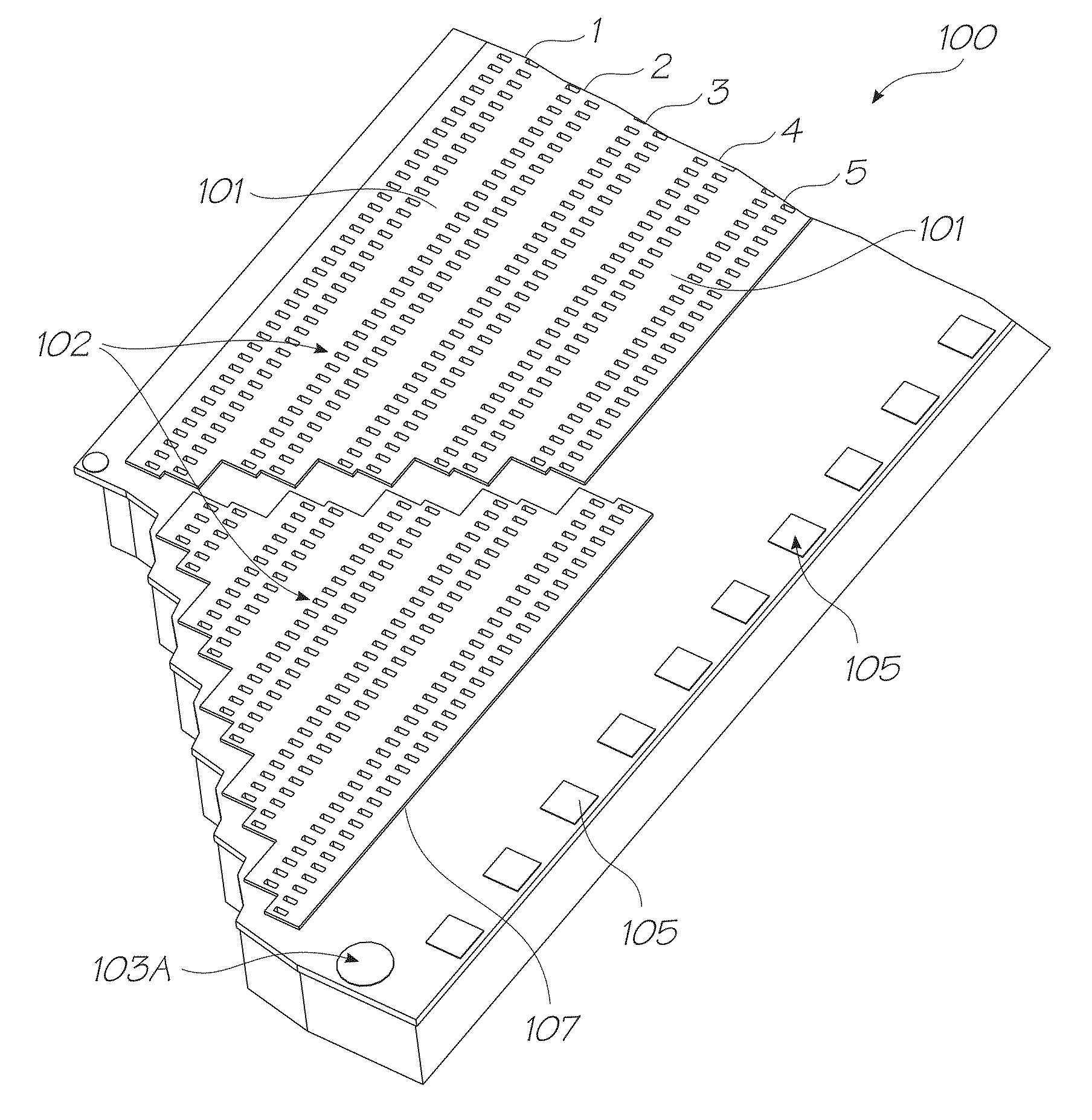
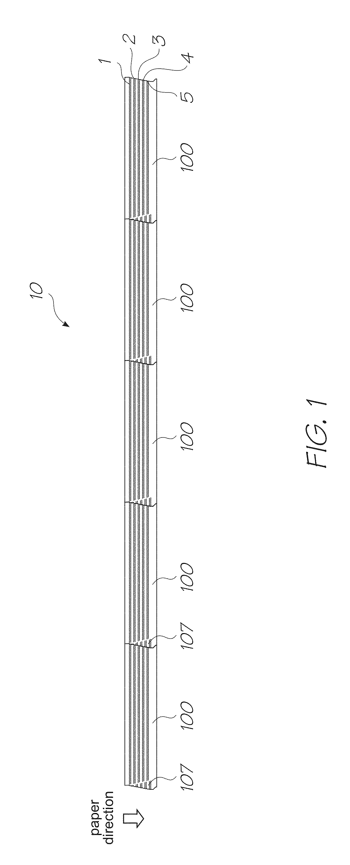
[0071]Referring to FIG. 1, the Memjet® printhead 10 is a pagewidth printhead comprised of a plurality of printhead integrated circuits (ICs) 100 butted end-on-end. Each printhead integrated circuit 100 typically has a length of about 20 mm. The number of butting printhead ICs 100 in a particular printhead will, of course, depend on the type of printer. For example, a 4″ printhead (suitable for photo or label printing) typically comprises five abutting ICs 100, as shown...


PUM


Abstract

An inkjet printer includes an inkjet printhead having a plurality of color planes for ejecting a plurality of different inks. Each color plane has a nozzle row defined in a nozzle face of the printhead and each nozzle in a respective color plane is supplied with a same ink. The printhead is plumbed such that a first color plane ejecting a first ink having a relatively low luminance is sandwiched between second and third color planes ejecting respective second and third inks having a relatively high luminance. A plurality of ink reservoirs are in fluid communication with the printhead, the ink reservoirs containing the first, second and third inks. An amount of surfactant in the first ink is at least 0.4 wt % greater than an amount of surfactant in the second and third inks.

Description

PRIORITY[0001]This application claims priority under 35 U.S.C. 119(e) to U.S. provisional application No. 61 / 537,063 entitled “PRINTER FOR MINIMIZING ADVERSE MIXING OF HIGH AND LOW LUMINANCE INKS AT NOZZLE FACE OF INKJET PRINTHEAD,” filed on Sep. 21, 2011, the content of which is hereby expressly incorporated by reference in its entirety for all purposes.FIELD OF THE INVENTION[0002]This invention relates to inkjet printing and methods for improving print quality. It has been developed primarily for minimizing adverse color mixing on nozzle plates of inkjet printheads.BACKGROUND OF THE INVENTION[0003]The present Applicant has developed a plethora of thermal bubble-forming printheads and thermal bend-actuated printheads. The Applicant's thermal bubble-forming printheads include those with suspended heater elements (as described in, for example, U.S. Pat. No. 6,755,509; U.S. Pat. No. 7,246,886; U.S. Pat. No. 7,401,910; and U.S. Pat. No. 7,658,977, the contents of which are incorporated...

Claims


Application Information

Patent Timeline
Patent Type & Authority Patents(United States)
IPC IPC(8): B41J2/21
CPCC09D11/40B41J2/155C09D11/32B41J2/145B41J2202/20B41J2202/19B41J2/2103B41J2/2146B41J2/185B41J2/175B41J2/17509B41J29/02B41J2/1433B41J2/21
Inventor PRASHAR, JOGNANDAN KUMARBISSON, ADRIAN PETERBROWN, BRIAN ROBERTJERCEVIC, MILEJARAMILLO, GALO DAVID
Owner MEMJET TECH LTD
Learn More