
Multi-purpose hair cutter

a multi-purpose, hair cutting technology, applied in the field of hair cutting, can solve the problems of decreasing work efficiency and achieve the effect of improving cutting work efficiency

Inactive Publication Date: 2014-04-22
TOKYO RIKI
View PDF23 Cites 10 Cited by
  • Summary
  • Abstract
  • Description
  • Claims
  • Application Information

AI Technical Summary

Benefits of technology

[0007]It is another object of the present invention is to provide a multi-purpose hair cutter capable of improving work efficiency.
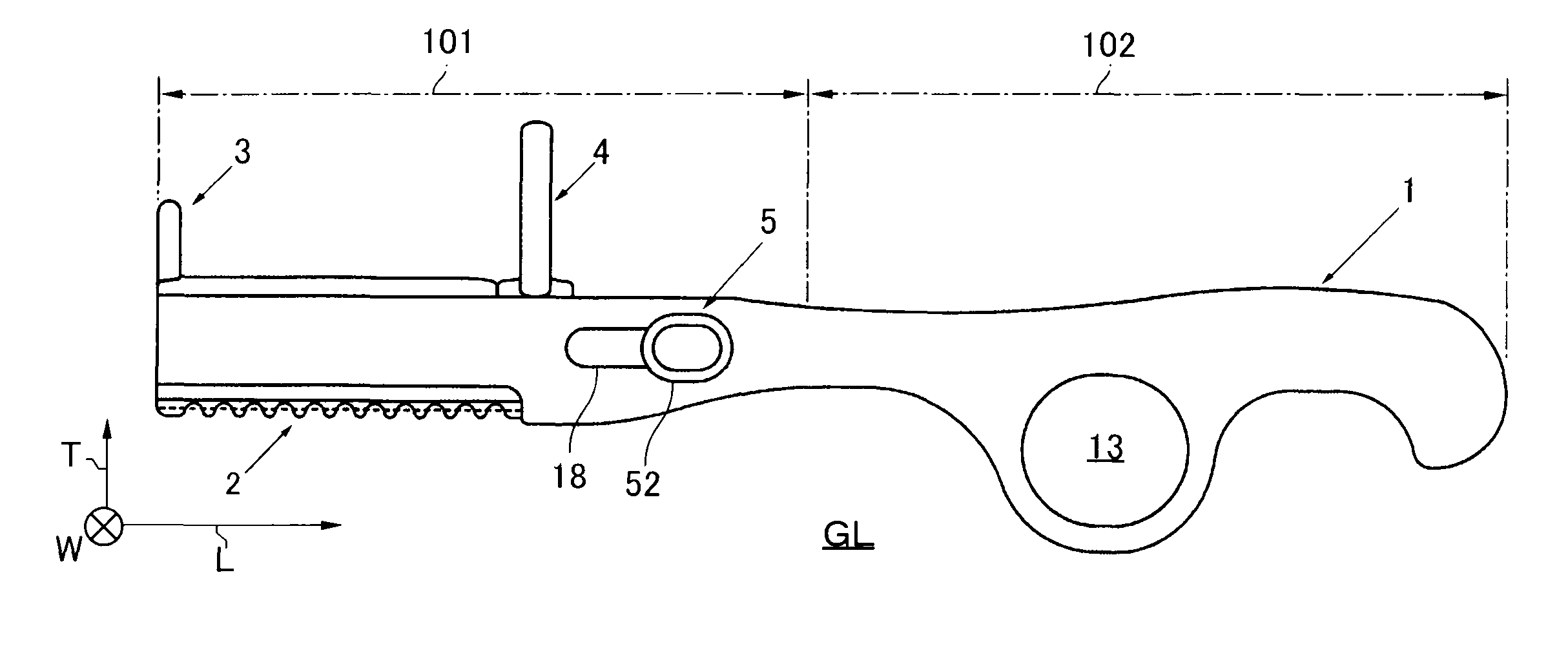
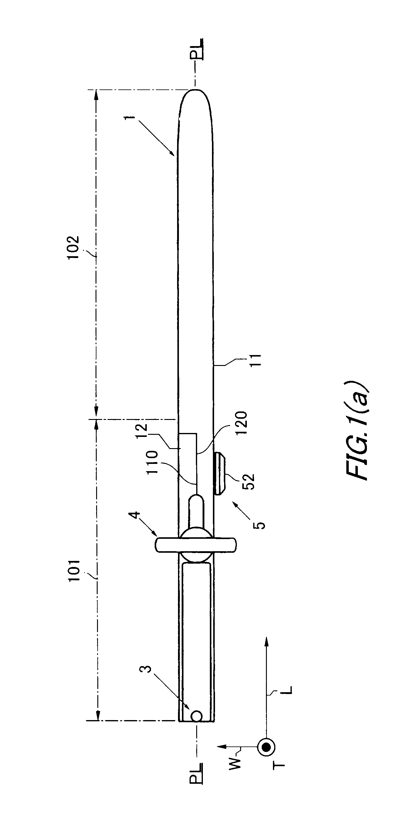
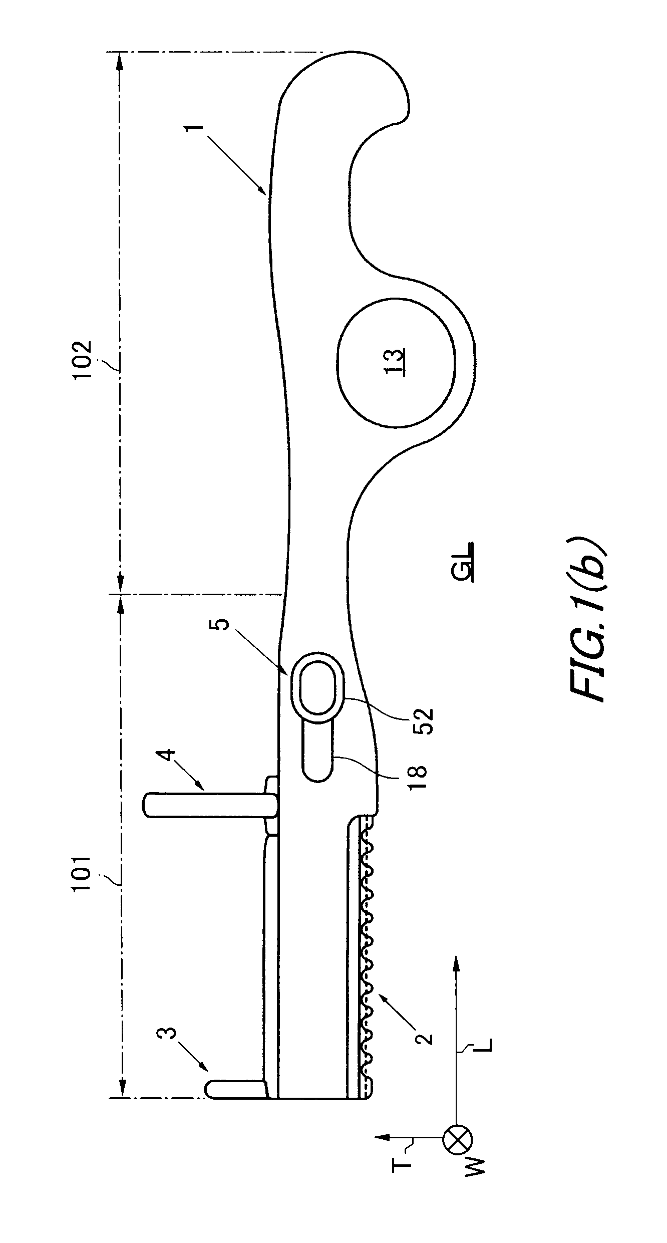
[0010]One feature of the present invention resides in that the projection member is provided in addition to the above-mentioned basic hair cutter structure. More specifically, the base part of the projection member is attached to the other side of the body member opposite to the blade member in the height direction, while the projecting part is formed to project from the base part and rises in a direction opposite to the blade member. With this structure, a part of the hair bundle held with the left hand, which should be left uncut, can be put aside in the above stroke cut by catching it with the projecting part upon swinging up the multi-purpose hair cutter held with the right hand. Accordingly, the multi-purpose hair cutter according to the present invention does not have a disadvantage of temporarily interrupting the up-and-down movement, improving the cutting work efficiency.

Problems solved by technology

In such a work procedure, however, the back-and-forth movement of the hair cutter is temporarily interrupted upon putting aside a part of the hair bundle, decreasing work efficiency.

Method used


Image

  • Multi-purpose hair cutter
  • Multi-purpose hair cutter
  • Multi-purpose hair cutter

Examples


Embodiment Construction

[0034]In FIGS. 1 to 22, the same or corresponding portions are indicated by the same symbols. Throughout the description with reference to FIGS. 1 to 22, since the longitudinal direction of the body member, the longitudinal direction of the blade member, the longitudinal direction of the projection member, and the longitudinal direction of the finger rest member all coincide with each other, they are all indicated by a symbol L. Also, since the lateral direction of the blade member, the height direction of the projection member, and the height direction of the finger rest member all coincide with each other, they are all indicated by a symbol T. Moreover, since the width direction of the body member, the width direction of the blade protector, the width direction of the projection member, and the radial direction of the finger rest member all coincide with each other, they are all indicated by a symbol W.

[0035]The multi-purpose hair cutter of FIGS. 1(a) and 1(b) includes a body memb...


PUM


Abstract

A multi-purpose hair cutter according to the present invention includes a body member, a blade member, and a projection member. The blade member is attached to a first side of the body member in a height direction. The projection member has a base part and at least one projecting part. The base part is attached to a second side of the body member opposite to the blade member in the height direction. The projecting part is formed to project from the base part and rises in a direction opposite to the blade member.

Description

TECHNICAL FIELD[0001]The present invention relates to a hair cutter and particularly relates to a multi-purpose hair cutter having many functions.BACKGROUND OF THE INVENTION[0002]As one of hairdressing tools important for hairdressers or hair stylists, there has been known a hair cutter such as disclosed in Japanese Patent No. 3182554.[0003]The hair cutter of this type makes it possible to realize a variety of hair designs with a haircut method different from that for a conventional hairdressing scissors. In a stroke cut using a hair cutter, for example, an adequate amount of hair is first brushed into a hair bundle using a comb or the like, and the obtained hair bundle is then held with the left hand and the held hair bundle is downwardly combed and thinned by moving the hair cutter up and down with the right hand. This stroke cut makes it possible to comb and thin the hair at an angle following the natural direction of the hair.[0004]In the above stroke cut, however, it is sometim...

Claims


Application Information

Patent Timeline
Patent Type & Authority Patents(United States)
IPC IPC(8): B26B21/10A45D24/36
CPCB26B21/12
Inventor HIRANO, TORU
Owner TOKYO RIKI
Learn More