Sound direction estimation apparatus and sound direction estimation method
a technology of sound direction estimation and sound source, which is applied in direction finders, direction finders using ultrasonic/sonic/infrasonic waves, direction finders, etc., can solve the problem of not being able to estimate the direction of a specific class of sound sources, and achieve high precision
- Summary
- Abstract
- Description
- Claims
- Application Information
AI Technical Summary
Benefits of technology
Problems solved by technology
Method used
Image
Examples
first embodiment
[0046]Hereinafter, a first embodiment of the invention will be described with reference to the accompanying drawings.
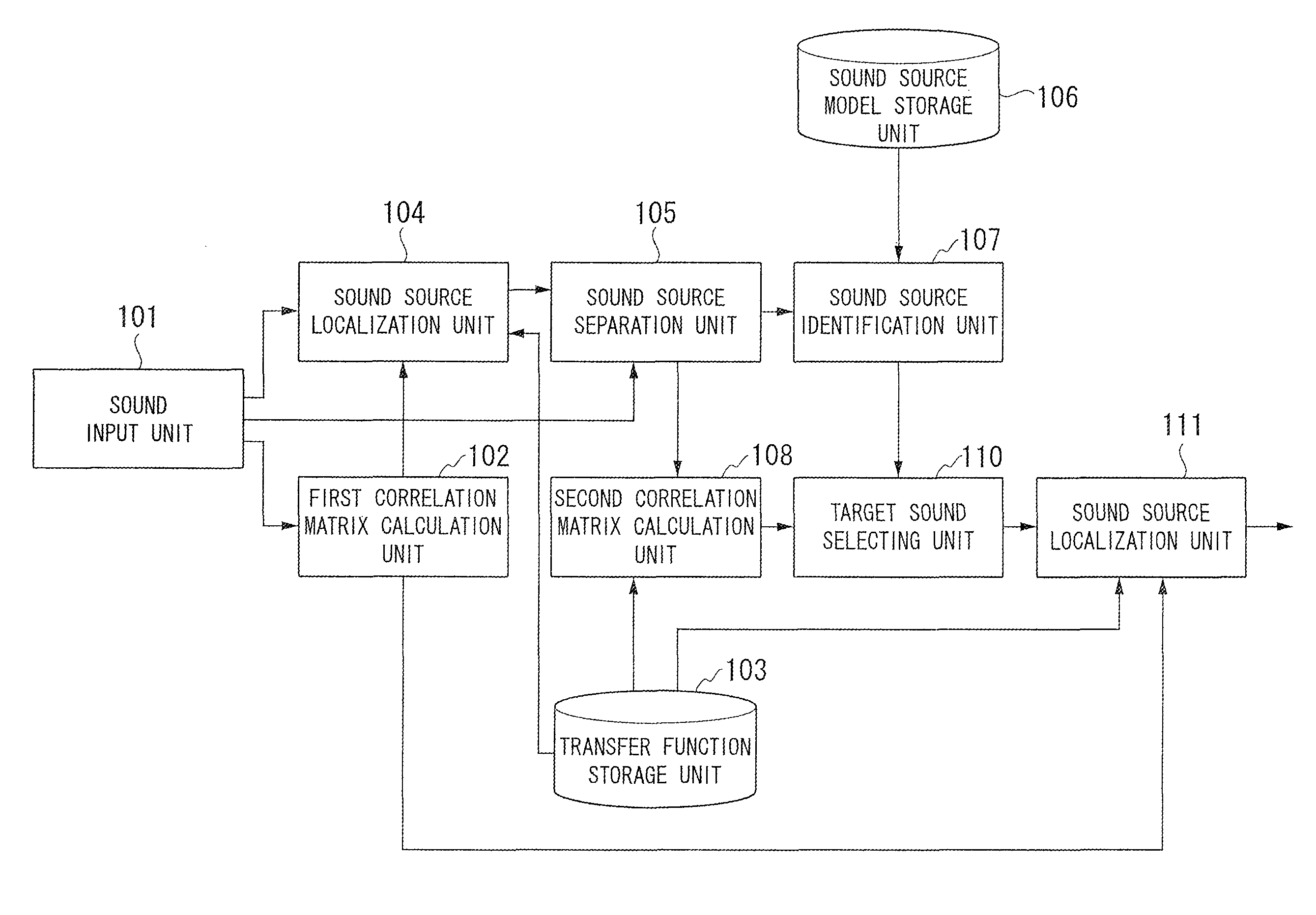
[0047]FIG. 1 is a diagram schematically illustrating the configuration of a sound direction estimation apparatus 1 according to the first embodiment of the invention. The sound direction estimation apparatus 1 includes a sound input unit 101, a first correlation matrix calculation unit 102, a transfer function storage unit 103, a sound source localization unit 104, a sound source separation unit 105, a sound source model storage unit 106, a sound source identification unit 107, a second correlation matrix calculation unit 108, a target sound selecting unit 110, and a sound source localization unit 111.
[0048]In this configuration, the sound source localization unit 104 estimates first sound direction information as primary candidates using a multiple signal classification (MUSIC) method. Note that a general MUSIC method may be referred to as a standard eigenvalue decom...
second embodiment
[0186]Hereinafter, a second embodiment of the invention will be described with reference to the accompanying drawings.
[0187]FIG. 8 is a diagram schematically illustrating the configuration of a sound direction estimation apparatus 2 according to the second embodiment of the invention.
[0188]The sound direction estimation apparatus 2 includes a sound input unit 101, a first correlation matrix calculation unit 102, a transfer function storage unit 103, a sound source localization unit 104, a sound source separation unit 105, a sound source model storage unit 106, a sound source identification unit 107, a second correlation matrix calculation unit 208, a correlation matrix information storage unit 209, a target sound selecting unit 110, a sound source localization unit 211, and a transfer function storage unit 212.
[0189]That is, the sound direction estimation apparatus 2 is different from the sound direction estimation apparatus 1 shown in FIG. 1, in that the second correlation matrix c...
third embodiment
[0241]Hereinafter, a third embodiment of the invention will be described with reference to the accompanying drawings.
[0242]FIG. 12 is a diagram schematically illustrating the configuration of a sound direction estimation apparatus 3 according to the third embodiment of the invention.
[0243]The sound direction estimation apparatus 3 includes a sound input unit 101, a first correlation matrix calculation unit 102, a transfer function storage unit 103, a sound source localization unit 104, a sound source separation unit 105, a sound source model storage unit 106, a sound source identification unit 107, a second correlation matrix calculation unit 308, a correlation matrix information storage unit 209, a target sound selecting unit 310, a sound source localization unit 211, and a transfer function storage unit 212.
[0244]That is, the sound direction estimation apparatus 3 is different from the sound direction estimation apparatus 1 shown in FIG. 1, in that the second correlation matrix ca...
PUM
 Abstract
Description
Claims
Application Information
 - R&D
- Intellectual Property
- Life Sciences
- Materials
- Tech Scout
- Unparalleled Data Quality
- Higher Quality Content
- 60% Fewer Hallucinations
Browse by: Latest US Patents, China's latest patents, Technical Efficacy Thesaurus, Application Domain, Technology Topic, Popular Technical Reports.
© 2025 PatSnap. All rights reserved.Legal|Privacy policy|Modern Slavery Act Transparency Statement|Sitemap|About US| Contact US: help@patsnap.com


