
Method and arrangement for efficiently generating current with a high rate of change

Active Publication Date: 2014-04-08
EFORE TELECOM FINLAND OY
View PDF31 Cites 16 Cited by
  • Summary
  • Abstract
  • Description
  • Claims
  • Application Information

AI Technical Summary

Benefits of technology

The aim of this patent is to develop a solution to make electricity generation more effective, including the generation of high frequency components.

Problems solved by technology

However, as a disadvantage they have high dissipation i.e. low efficiency.
However, in the switch-mode power supplies it also necessary to use inductive components for coupling between different voltage levels, which causes slowness because the current of inductive components, such as an inductor, cannot change unlimitedly fast.
In some particular applications, such as a radio transmitters having good linearity, a fixed operating voltage nevertheless causes poor efficiency.
This kind of arrangement creates a low total efficiency, and lately methods have been evolved to improve this.
In practice, the limited speed of the switch-mode converter causes an upper limit for the frequency of an alternating current component of efficiently generated electricity.
In these applications the prior art solutions cannot either generate adequate high frequency electricity components with sufficiently high efficiency.
It can be generally stated that the known methods for generating electricity are not able to generate electricity including components of sufficiently high frequency, with sufficiently high efficiency.

Method used


Image

  • Method and arrangement for efficiently generating current with a high rate of change
  • Method and arrangement for efficiently generating current with a high rate of change
  • Method and arrangement for efficiently generating current with a high rate of change

Examples


Embodiment Construction

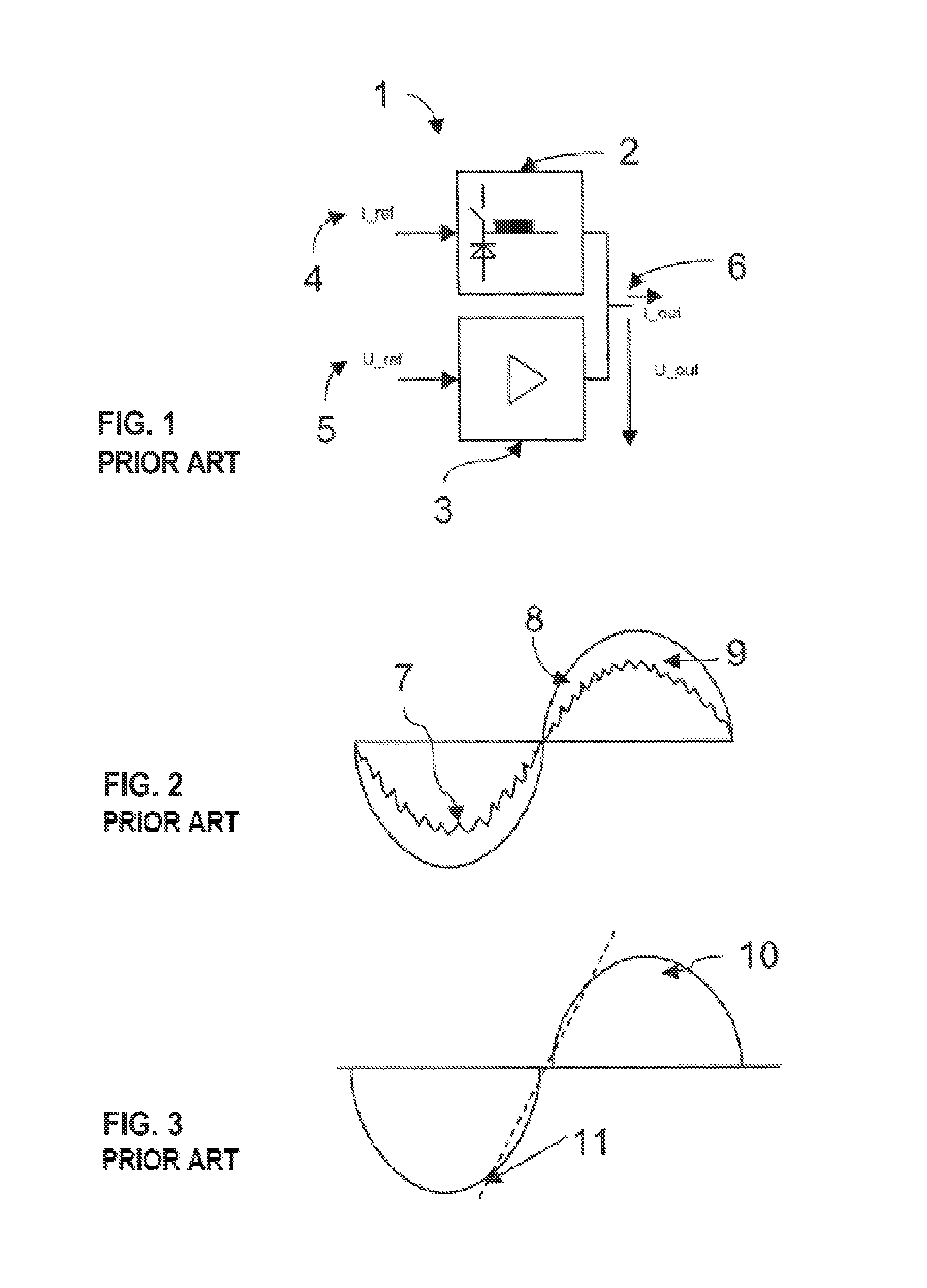
[0021]FIG. 1 illustrates a commonly known envelope tracking circuit 1, which consist of a parallel connection of a switch-mode converter 2 and a linear power supply 3. A current instruction 4 is input to the switch-mode converter 2 and a voltage instruction 5 is entered to the linear power supply 3, respectively, in which case desired output voltage and output current can be generated to the output point 6. A greater part of the output current is generated by the switch-mode converter 2, so high power dissipation is not created in the linear power supply 3. This is because the power dissipation of the linear power supply is proportional to the product of the voltage which influences across the linear power supply, and the pass-through current, whereby the current is zero in an ideal case when the current is passing through the switch-mode converter.

[0022]FIG. 2 illustrates the generating of an alternating component of output current in FIG. 1. The main part of the output alternating...


PUM


Abstract

The invention relates to power supplies where the output current is controllable. In prior art, there is a problem to provide both high rate of change in the current output and high efficiency. The solution of the present invention is based on combining current elements, whereby the current is controlled by switching the outputs of the current elements. The current elements can be implemented with e.g. buck converters, whereby the power dissipation is small.

Description

[0001]The invention relates to power supplies where the output current is controllable. The invention can be applied e.g. for providing supply current for radio transmitters etc.BACKGROUND OF THE INVENTION[0002]Various operating voltages are needed in electronic systems. Usually these operating voltages are generated by so called power supplies. Generally, power supplies are divided into so called linear power supplies and so called switch-mode power supplies. Power semiconductors are used in linear power supplies in so called linear state, i.e. both the current and the voltage affect simultaneously across them. The values of the current and the voltage change linearly when moving from one operating point to another. The advantages of the linear power supplies are fast response and accurate adjustment, by which e.g. accurate and fast adjustment of the output voltage is achieved. However, as a disadvantage they have high dissipation i.e. low efficiency. The dissipation is directly pr...

Claims


Application Information

Patent Timeline
IPC IPC(8): G05F1/00
CPCH02M7/42H02M3/1584
Inventor RITAMAKI, SEPPOSIPPOLA, MIKA
Owner EFORE TELECOM FINLAND OY
Learn More