
Fluidics based pulsatile perfusion preservation device and method

a technology of tissue perfusion and fluidics, which is applied in the field of methods and apparatus for the preservation of living tissues, can solve the problems of limited success of tissue perfusion in the atmosphere, limited tissue viability, and the technique for tissue preservation has not become normalized

Active Publication Date: 2014-04-01
BOARD OF RGT THE UNIV OF TEXAS SYST
View PDF34 Cites 0 Cited by
  • Summary
  • Abstract
  • Description
  • Claims
  • Application Information

AI Technical Summary

Problems solved by technology

Although tissue transplantation and implantation have been viable since the 1960's, and have increased in popularity since that time, techniques for preservation of tissue have not become normalized.
A disadvantage of nonperfused cold storage, however, is the limited period of viability of the tissue, typically due to significant oxygen decline in the storage medium resulting from the stored tissue's metabolic need for oxygen.
However, only limited success has been achieved with perfusion of tissue in the atmosphere (i.e., without submersing the perfused tissue in the perfusate).
The danger of this method of perfusion is that a pressure gradient may develop across the capillary wall of the tissue, which is proportionate to the output of the perfusion pump.
Under hypothermic conditions, perfusion pressures in excess of 20 mm Hg have resulted in capillary damage destroying and compromising the viability of the tissue being preserved.
However, hypothermia alone is less protective than when it is combined with oxygenated perfusion, in that a continuous supply of oxygen is available in the latter case to support the metabolic oxygen requirements.
However, devices that are currently available for hypothermic pulsatile perfusion are typically large, require significant volumes of compressed gas and electrical power, and / or also may necessitate an upright level orientation for operation.
Additionally, these devices tend to be very complex, consisting of many intricate parts that must work precisely in concert.

Method used


Image

  • Fluidics based pulsatile perfusion preservation device and method
  • Fluidics based pulsatile perfusion preservation device and method
  • Fluidics based pulsatile perfusion preservation device and method

Examples


Embodiment Construction

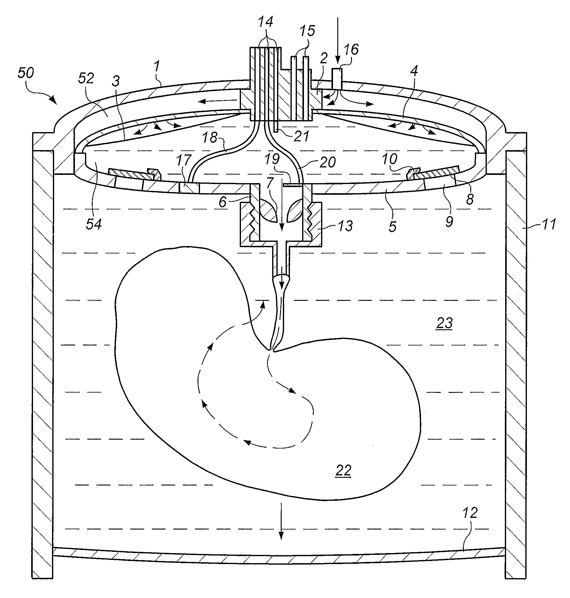
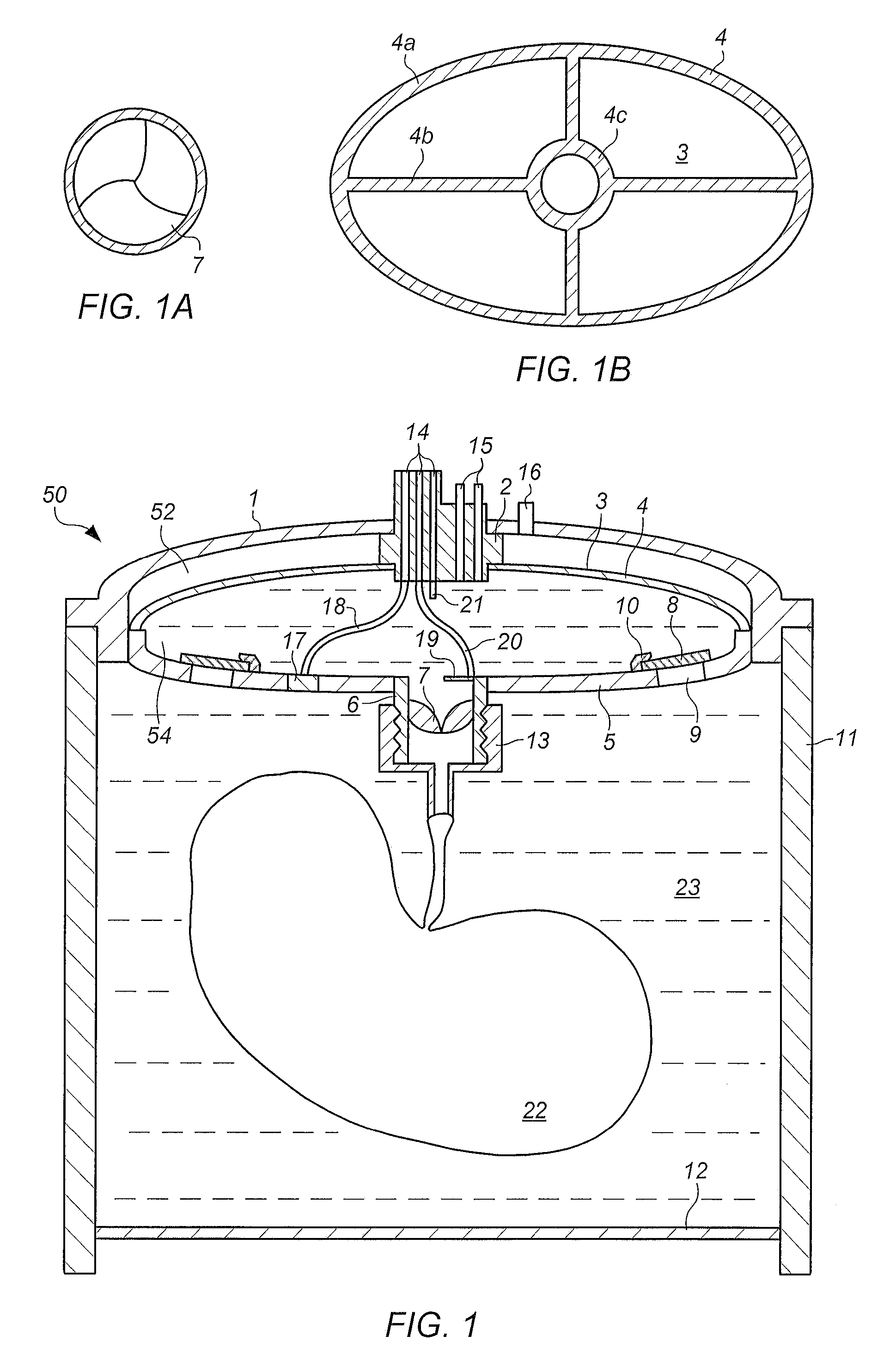
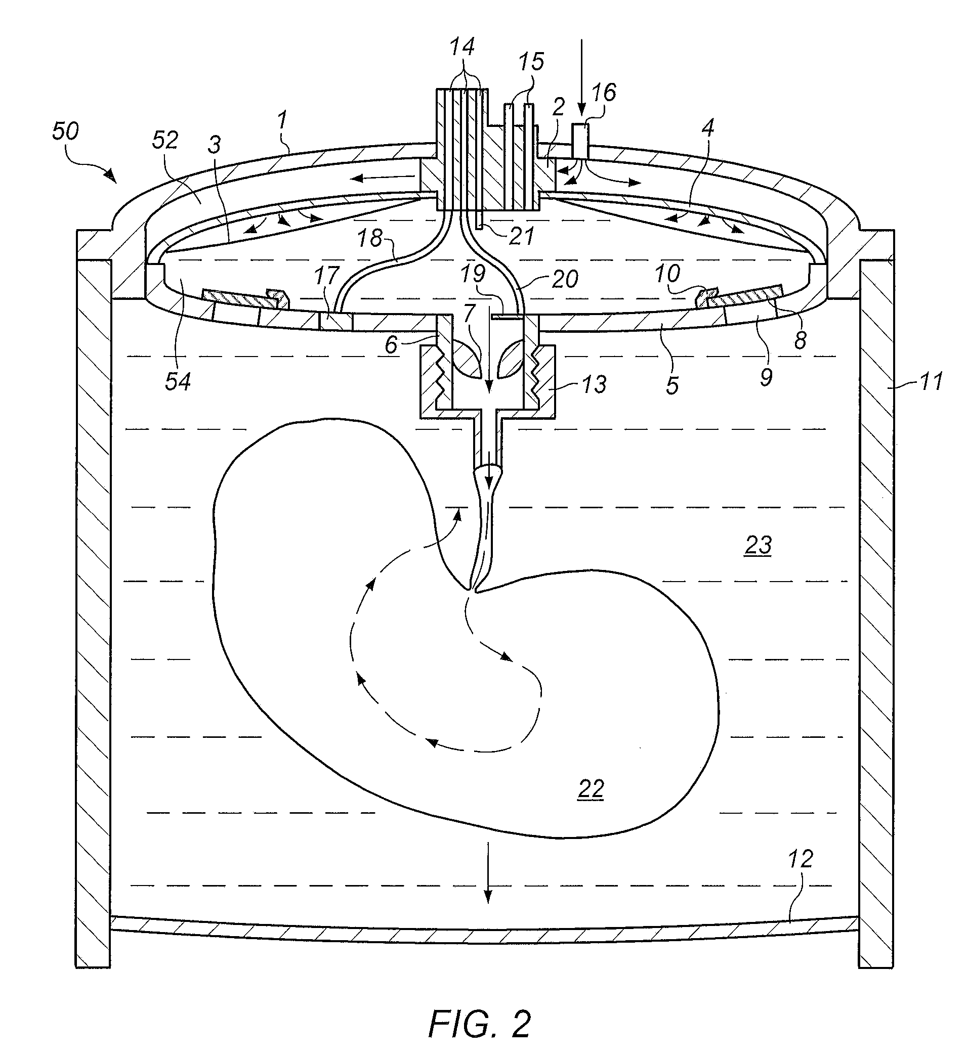
[0032]Turning now to the drawings, FIG. 1 is a cross-section view of an embodiment of a preservation apparatus for preserving extracorporeal living tissue and organs. The preservation apparatus includes a storage compartment 23 defined by walls 11 and bottom 12. Storage compartment 23 is capable of receiving living tissue and organs 22. The apparatus also includes a cover assembly 50 composed of a lid 1, a support element 5, and a gas permeable membrane 3 disposed between support element 5 and lid 1. When assembled cover assembly 50 together with storage compartment 23 define a storage chamber. Gas permeable membrane 3 in combination with lid 1 defines a pumping chamber 52. In combination with support element 5, gas permeable membrane 3 also defines a perfusion chamber 54.

[0033]An oxygen containing gas source is coupled to pumping chamber 52 of the apparatus through port 16. In use, the tissue or organ 22 is submerged in a preservation fluid in the storage compartment 23. The oxygen...


PUM


Abstract

In one embodiment, a preservation apparatus is described that includes a storage compartment. The storage compartment is configured to hold an organ or tissue and a preservation fluid. A cover assembly is configured to engage the storage compartment. The cover assembly includes a support element, wherein the support element together with the storage compartment define a storage chamber. The cover assembly also includes a lid and a gas permeable membrane disposed between the lid and the support element. The gas permeable membrane and the support element together define a perfusion chamber configured to hold preservation fluid and an organ or tissue during use.

Description

PRIORITY CLAIM[0001]This application claims the benefit of U.S. Provisional Application No. 61 / 245,762 filed on Sep. 25, 2010.BACKGROUND OF THE INVENTION[0002]1. Field of the Invention[0003]The invention generally relates to a method and apparatus for the preservation of living tissues, particularly organs.[0004]2. Description of the Relevant Art[0005]Although tissue transplantation and implantation have been viable since the 1960's, and have increased in popularity since that time, techniques for preservation of tissue have not become normalized. Initially, simple cold storage was used where the tissue was maintained in a cold, nonperfused preservation fluid. Perfused cold storage and hyperbaric cold perfused storage were subsequently shown experimentally to be superior to simple nonperfused cold storage. Since neither perfused cold storage nor hyperbaric cold perfused storage could be practically applied, nonperfused cold storage continued to be preferred. A disadvantage of nonper...

Claims


Application Information

Patent Timeline
Patent Type & Authority Patents(United States)
IPC IPC(8): A01N1/02A01N1/00
CPCA01N1/0247
Inventor BUNEGIN, LEONIDGELINEAU, EDWARD F.
Owner BOARD OF RGT THE UNIV OF TEXAS SYST
Learn More