Systems and methods for improved visual field testing

a visual field and test system technology, applied in the field of visual field testing, can solve the problems of confounding visual field test, incomplete or partial closure of eyelids during stimulus presentation, interference with visual field measurement, etc., and achieve the effect of greater confidence in results

Active Publication Date: 2014-04-01
CARL ZEISS MEDITEC INC
View PDF25 Cites 13 Cited by
  • Summary
  • Abstract
  • Description
  • Claims
  • Application Information

AI Technical Summary

Benefits of technology

The present invention provides a system that records images of the eye during a visual field test and stores them for review. This helps the doctor identify potential causes of visual field defects, such as gaze errors or blocked eyelid, and determine if the results are reliable. The system also allows the doctor to associate the images with specific test locations and measurements on the gaze error plot, increasing their confidence in the results. Overall, this system improves the accuracy and reliability of visual field testing.

Problems solved by technology

Similarly, complete or partial closure of the eyelids during stimulus presentation also can interfere with visual field measurement.
Perhaps less obviously, imprecise translational (x, y and z) and / or rotational placement of the eye relative to the trial lens can also confound visual field test results.
Unfortunately, the operator may be either periodically absent or attending other tasks which divert his attention from the video presentation.
Further, the operator cannot determine gaze direction from the video display and typically is unaware of when the actual point is presented, the only time when gaze direction is important.
While useful, this method is problematic in that the anatomic blind spot is not always where predicted, which can lead to erroneous recordings of fixation losses.
However, if the sensitivity is lower than normal, that result might have happened because of genuine loss of visual sensitivity, or because—during one or more of the stimulus presentations required to determine threshold sensitivity—the eye was not centered behind the trial lens holder (thus allowing the trial lens holder to block the patient's vision in that part of the visual field), or the head and eye were tilted around the visual axis, allowing the stimulus to be presented at the wrong retinal location, or because the eyelid was partially or completely closed, or because the patient was not looking where s / he was supposed to be looking.
Clinical gaze trackers provide only limited quantitative gaze error data and may not quantify other types of issues, e.g., partial eyelid closure or trial lens blocking parts of the field of view.
Furthermore, there is no way for the doctor to retrospectively determine the cause of a depressed measurement.

Method used


Image

  • Systems and methods for improved visual field testing
  • Systems and methods for improved visual field testing
  • Systems and methods for improved visual field testing

Examples


Embodiment Construction

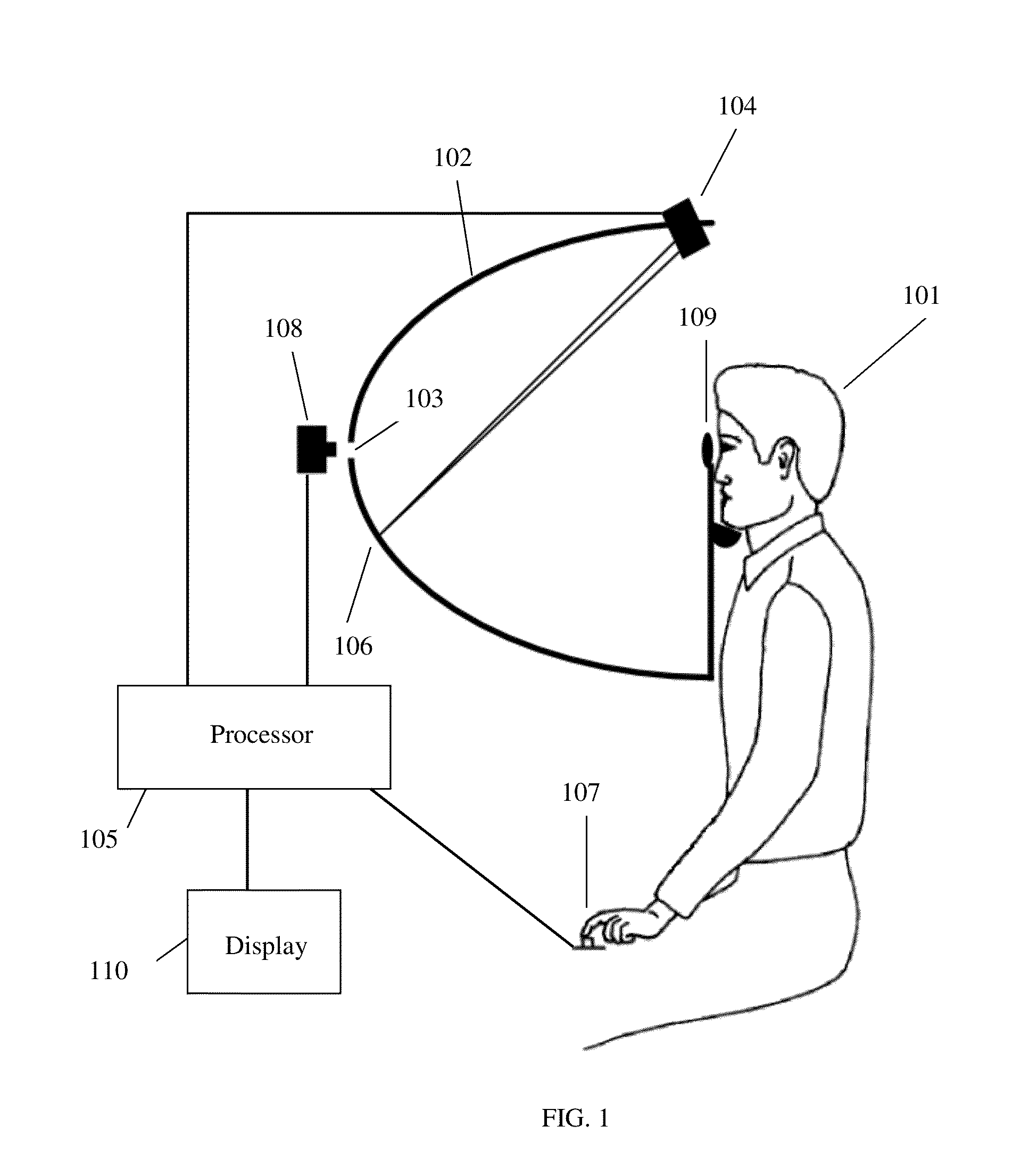
[0012]The invention described herein could be used in conjunction with any type of visual field tester. One such system is illustrated in FIG. 1. A patient 101 is shown observing a hemispherical projection screen 102. The patient is instructed to fixate at a point at the center of the hemispherical screen 103. A projector 104 under control of a processor 105 projects a series of spots 106 onto the screen. The patient indicates that the spot 106 of light was seen by depressing button 107. The response is recorded by the processor 105. A camera 108 can be used to monitor the gaze of the patient throughout the test. The images from the gaze camera can optionally be displayed (on display 110) to the clinician for aid in patient alignment or test verification. A trial lens holder 109 is positioned in front of the eye of the patient being tested to correct the refractive error of the patient. While FIG. 1 shows a projection type visual field tester, the subject invention can be used with ...


PUM


Abstract

Systems and methods for improving the reliability of visual field test results are presented. In one embodiment, images of the eye are recorded during the presentation of visual stimuli and are displayed to the user to provide information on eye motion, eye position relative to trial lens, and eyelid closure during the test. Individual or combined images can be displayed for individual stimuli, specific test points, or points in the gaze trace in various embodiments of the invention.

Description

PRIORITY[0001]This application claims priority to U.S. Provisional Application Ser. No. 61 / 480,300, filed Apr. 28, 2011, hereby incorporated by reference.TECHNICAL FIELD[0002]This invention relates to the field of visual field testing. In particular, the invention discloses systems and methods to improve reliability of visual field test results.BACKGROUND[0003]Several approaches have been made to monitor and report errors in fixation, eyelid closure, and patient misalignment during visual field measurements in an effort to improve the reliability of visual field testing. Maintaining steady fixation on the central target is vital to accurate mapping of the visual field and for comparing follow-up tests over time. Similarly, complete or partial closure of the eyelids during stimulus presentation also can interfere with visual field measurement. Perhaps less obviously, imprecise translational (x, y and z) and / or rotational placement of the eye relative to the trial lens can also confou...

Claims


Application Information

Patent Timeline
IPC IPC(8): A61B3/02A61B3/00
CPCA61B3/024
Inventor JOHANSSON, GORAN ANDERSFITZMORRIS, THOMAS K.PATELLA, VINCENT MICHAEL
Owner CARL ZEISS MEDITEC INC
Why Eureka
Try Eureka