
Apparatus and method for detecting signal in a spatial multiplexing multiple input multiple output communication system

a communication system and signal detection technology, applied in the field of apparatus and a communication system for detecting signals, can solve the problems of difficult to achieve the actual implementation of sphere decoding schemes, and large performance degradation of osic schemes in comparison with ml schemes. achieve the effect of reducing the calculation complexity of signal reception devices

Active Publication Date: 2014-03-25
SAMSUNG ELECTRONICS CO LTD +1
View PDF5 Cites 2 Cited by
  • Summary
  • Abstract
  • Description
  • Claims
  • Application Information

AI Technical Summary

Benefits of technology

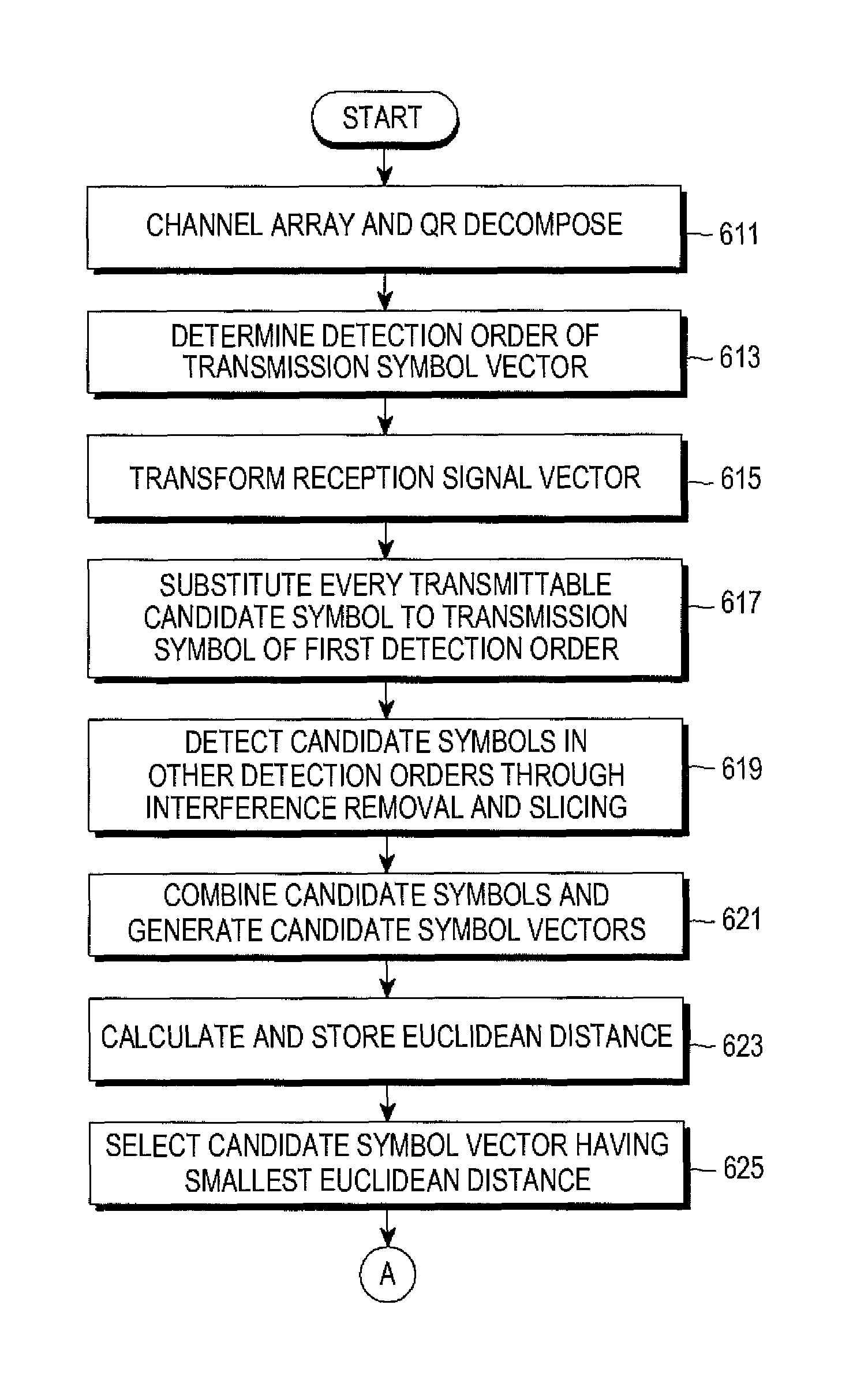
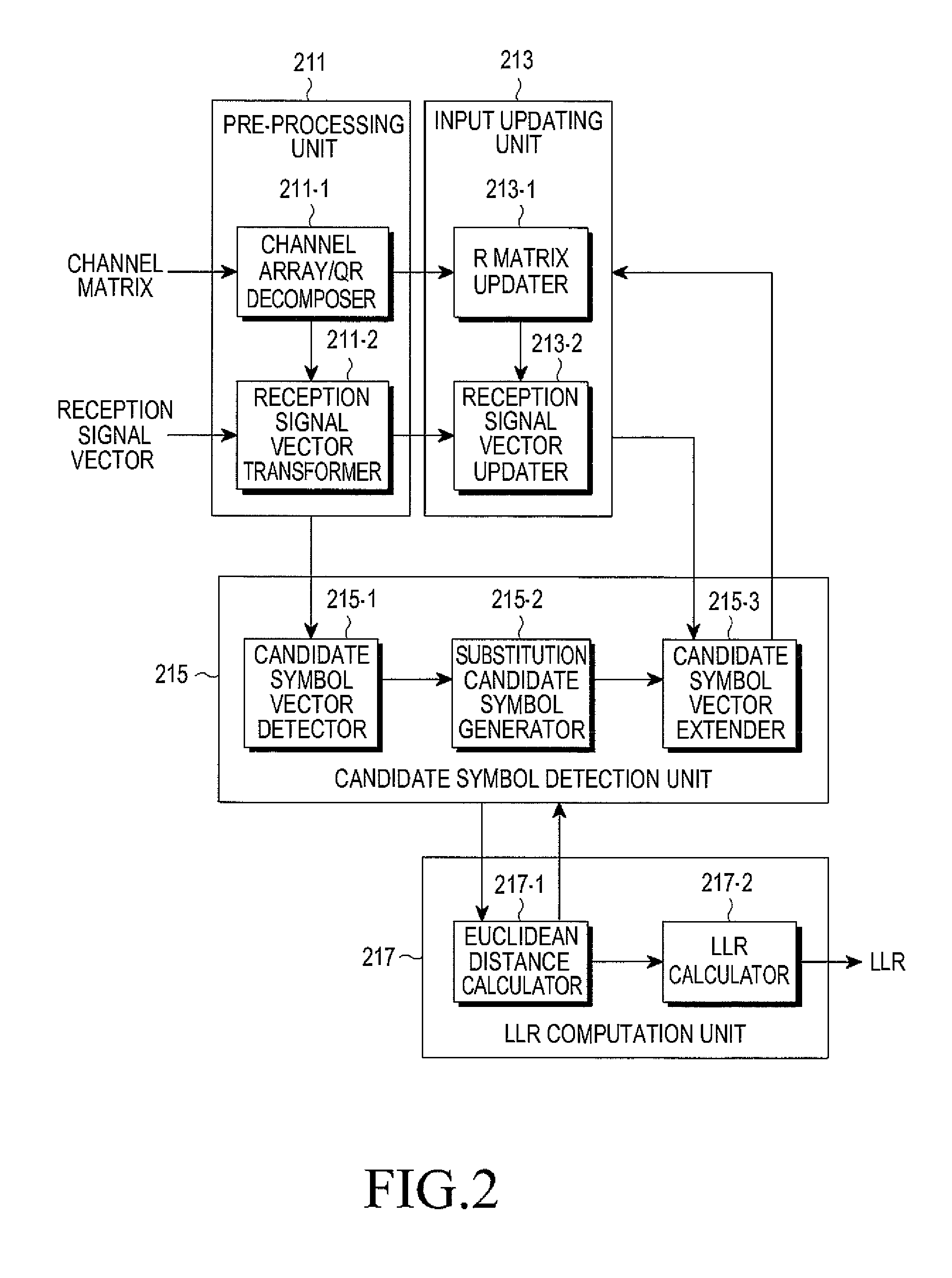
The present invention provides a method for detecting signals in a communication system more efficiently and accurately while reducing the complexity of the signal reception device. This is achieved by diversifying the detection orders, generating alternative symbols to replace the first order, and calculating the likelihood ratio (LLR) value for each order. This approach performs as well as the maximum likelihood (ML) soft-decision scheme but with significantly lower computation complexity.

Problems solved by technology

The ZF scheme and the MMSE scheme have lower complexity, but their performance deterioration is very large in comparison with the ML scheme.
Further, the OSIC scheme generates more performance deterioration in comparison with the ML scheme.
Further, the sphere decoding scheme has identical performance to the ML scheme, but it has difficulty in obtaining a radius of an initial sphere and it requires very large calculation quantity in consideration of the worst channel condition such that it is difficult to achieve the actual implementation of the sphere decoding scheme.
Further, the QRD-M scheme has performance that greatly differs according to the number of candidate groups, such that the multiple candidate groups are required so as to obtain performance identical to that of the ML scheme, and in the event of considering the multiple candidate groups, the calculation complexity in the QRD-M scheme increases.
Especially, when the signal reception device uses the sphere decoding scheme, the large number of candidate groups of the detected signals are used for the performance improvement and thus the calculation complexity also increases.
However, a corresponding bit may be null in the candidate group, which may make it impossible to detect the LLR value.
Various schemes for estimating the Euclidean distance of the null bit have been suggested, but they have still include a limitation in the accuracy aspect, so that it may be impossible to generate the optimum LLR value.
As described above, the signal detection schemes suggested in the SM-MIMO communication system have deteriorated performance and increased calculation complexity in a process of the LLR value generation, as well as a process of the signal detection, in comparison with the ML scheme.

Method used


Image

  • Apparatus and method for detecting signal in a spatial multiplexing multiple input multiple output communication system
  • Apparatus and method for detecting signal in a spatial multiplexing multiple input multiple output communication system
  • Apparatus and method for detecting signal in a spatial multiplexing multiple input multiple output communication system

Examples


Embodiment Construction

[0022]FIGS. 1 through 7, discussed below, and the various embodiments used to describe the principles of the present disclosure in this patent document are by way of illustration only and should not be construed in any way to limit the scope of the disclosure. Those skilled in the art will understand that the principles of the present disclosure may be implemented in any suitably arranged communication system. Further, in the following description of the present invention, a part necessary for understanding an operation according to the present invention will be described, and a detailed description of known functions and configurations incorporated herein will be omitted when it may make the subject matter of the present invention rather unclear.

[0023]The present invention relates to an apparatus and a method for detecting a signal in a communication system using a Spatial Multiplexing Multiple Input Multiple Output (SM-MIMO) scheme (hereinafter, referred to as the ‘SM-MIMO communi...


PUM


Abstract

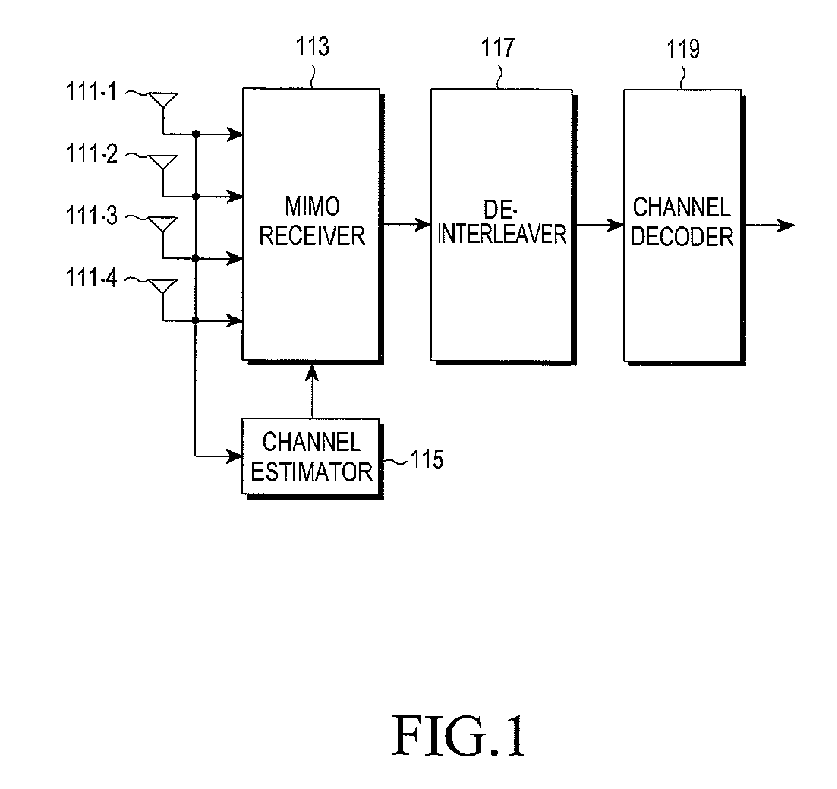
A Spatial Multiplexing Multiple Input Multiple Output (SM-MIMO) communication system, which generates Q and R matrices through QR decomposing a channel matrix in an array order corresponding to an order of transmission antennas of a signal transmission device, determines a detection order of transmission symbols included in a transmission symbol vector, QR decomposes a reception signal vector and generates the QR decomposed reception signal vector as a transformed reception signal vector, substitutes all of transmittable candidate symbols for a transmission symbol corresponding to a first detection order among the transmission symbols and sequentially removes interference in the transformed reception signal vector, detects candidate symbols of transmission symbols corresponding to a remaining detection order from the interference-removed transformed reception signal vector, combines the detected candidate symbols, detects candidate symbol vectors, and calculates Log-Likelihood Ratio values of bits included in the transmission symbols by using the detected vectors.

Description

CROSS-REFERENCE TO RELATED APPLICATION(S) AND CLAIM OF PRIORITY[0001]The present application is related to and claims priority under 35 U.S.C. §119(a) to a Korean Patent Application entitled “Apparatus and Method for Detecting Signal in a Spatial Multiplexing Multiple Input Multiple Output Communication System” filed in the Korean Industrial Property Office on Jan. 29, 2010 and assigned Serial No. 10-2010-0008791, the contents of which are incorporated herein by reference.TECHNICAL FIELD OF THE INVENTION[0002]The present invention relates to an apparatus and a method for detecting a signal in a communication system using a Spatial Multiplexing Multiple Input Multiple Output (SM-MIMO) scheme (hereinafter, referred to as the ‘SM-MIMO communication system’).BACKGROUND OF THE INVENTION[0003]The SM-MIMO communication system is a communication system employing the SM scheme and the MIMO scheme, and various signal detection schemes, such as the ML (Maximum Likelihood) scheme, the ZF (Zero ...

Claims


Application Information

Patent Timeline
Patent Type & Authority Patents(United States)
IPC IPC(8): H04L27/06H04L27/00
CPCH04L27/06H04B7/0413H04B7/0854H04L2025/03426H03M13/3927H04B7/0697H04L1/06
Inventor YANG, JOO-YEOLKIM, JAE-SEOKKIM, IN-HYOUNGJUNG, YUN-HOYEON, HAE-DONGKIM, KIL-HWANCHO, MI-SUK
Owner SAMSUNG ELECTRONICS CO LTD
Learn More