
Foam spray head assembly

a spray head and foam technology, applied in the direction of liquid transfer devices, instruments, single-unit apparatuses, etc., can solve the problems of difficult control of liquid volume and harmful to users, and achieve the effect of improving the sealing feature of the present invention, being more reliable and sensitiv

Active Publication Date: 2014-03-25
DERJIN (JIANGSU) PLASTIC PACKAGING CO LTD
View PDF30 Cites 11 Cited by
  • Summary
  • Abstract
  • Description
  • Claims
  • Application Information

AI Technical Summary

Benefits of technology

The invention is a new sealing device for a hydraulic system. It includes a movable wall that seals the inlet valve and a guide slot that allows air to pass through. The device also includes a contact neck and outlet that can control the movement of liquid. This design improves the sealing performance and makes the hydraulic system more reliable and sensitive.

Problems solved by technology

However, the amount of the liquid is difficult to control and the excess detergent may be harmful to the users when attached on the plates.

Method used


Image

  • Foam spray head assembly
  • Foam spray head assembly
  • Foam spray head assembly

Examples


Embodiment Construction

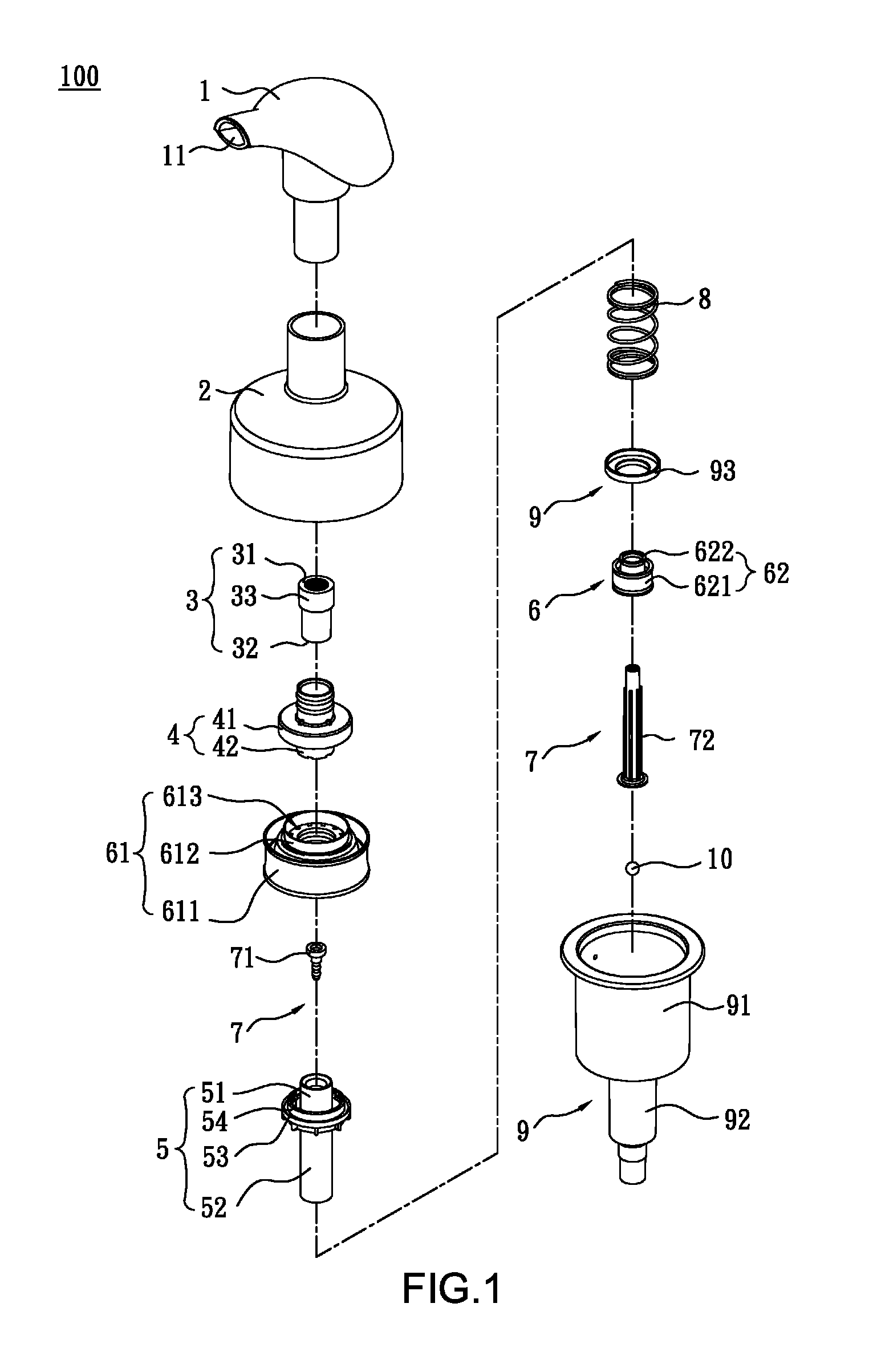
[0025]Referring to FIG. 1, the foam spray head assembly 100 of the present invention comprises a press head 1, a cap 2, a netted tube 3, a valve member 4, a main tube 5, a piston unit 6, a link unit 7, a resilient member 8, a cylinder unit 9 and a valve 10.

[0026]The press head 1 has a nozzle 11 for spraying the foam and the press head 1 is connected with the cap 2. The cap 2 has threads defined in the inner periphery thereof and the cap 2 is threadedly connected to a container. The netted tube 3 has a first net 31, a second net 32 and a hollow tube 33.

[0027]Referring to FIG. 1A, the valve member 4 has a first end and a second end, wherein the first end of the valve member 4 has a first recess 41, a second recess 42, an inlet valve 43 and a release path 44. The second end of the valve member 4 is connected with the netted tube 3. The inlet valve 43 is located in the first recess 41 and the release path 44 is located in the second recess 42.

[0028]As shown in FIG. 1B, the main tube 5 i...


PUM


Abstract

A foam spray head assembly includes a press head connected to a cap, a netted tube, a valve member, a main tube, a piston unit, a link unit, a resilient member, a cylinder unit and a valve. The netted tube is connected to the valve member. An outlet is defined between the first link of the link unit and the first tube. An inlet is defined between the second link of the link unit and the protrusion of the piston unit. The resilient member is mounted to the second tube and contacts the flange of the second tube. The first piston of the cylinder unit is movable in the first cylinder to form a sealed second chamber. The second piston of the cylinder unit is movable in the second cylinder to form a sealed third chamber. The valve is located in the passage of the second cylinder.

Description

BACKGROUND OF THE INVENTION[0001](1) Field of the Invention[0002]The present invention relates to a spray head assembly, and more particularly, to a foam spray head assembly with sealing feature.[0003](2) Description of the Prior Art[0004]The conventional liquid detergent is received in a container and a pump head is connected to the top of the container so as to suck the liquid from the container. When foam-type detergent is needed, the users generally get the liquid from the container by operating the pump head and then scrub the liquid to generate bubbles. However, the amount of the liquid is difficult to control and the excess detergent may be harmful to the users when attached on the plates. The same concern is also found when using shampoo or body gel.[0005]The present invention intends to provide an improved foam spray head assembly which can generate foam-type detergent for convenience of use.SUMMARY OF THE INVENTION[0006]The present invention relates to a foam spray head as...

Claims


Application Information

Patent Timeline
Patent Type & Authority Patents(United States)
IPC IPC(8): B67D7/76
CPCB05B11/304B05B7/0037B05B11/3047B05B11/3023B05B11/3074B05B11/3087B05B11/0075B67D7/76B05B11/1023B05B11/1047B05B11/1087B05B11/1074
Inventor WANG, YA-TSAN
Owner DERJIN (JIANGSU) PLASTIC PACKAGING CO LTD
Learn More