
Visible motion blur

a technology of motion blur and measurement method, which is applied in the field of measuring motion blur, can solve the problems of motion blur being a significant defect of most current display technology, motion blur arises, and none of these metrics attempts to provide a perceptual measure of the amount of motion blur

Inactive Publication Date: 2014-03-18
NASA
View PDF6 Cites 0 Cited by
  • Summary
  • Abstract
  • Description
  • Claims
  • Application Information

AI Technical Summary

Benefits of technology

The patent text describes a method for measuring motion blur, which is the blurring effect caused by the movement of objects in an image. The method involves analyzing the changes in brightness over time of a high-contrast moving edge. To measure the movement, two contrasts are calculated: one for the actual edge and one for an ideal step edge waveform with the same amplitude. These contrasts are then used to calculate a "motion blur" measure, which is a difference function. The method is based on the use of filters that mimic the human visual system, and is useful for analyzing images and video.

Problems solved by technology

Motion blur is a significant defect of most current display technologies.
Motion blur arises when the display presents individual frames that persist for significant fractions of a frame duration.
However, none of these metrics attempts to provide a perceptual measure of the amount of motion blur.
First, none of these metrics takes into account the contrast of the edge, and its effect upon perceived blur.
Second, contrast of the edge will mask the visibility of the blur [5, 6].
Finally, none of the existing metrics take into account the visual resolution of the display (pixels / degree of visual angle).

Method used


Image

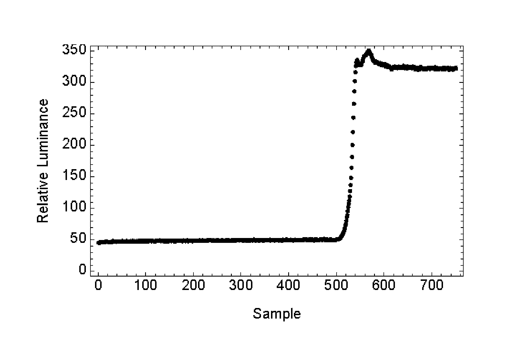
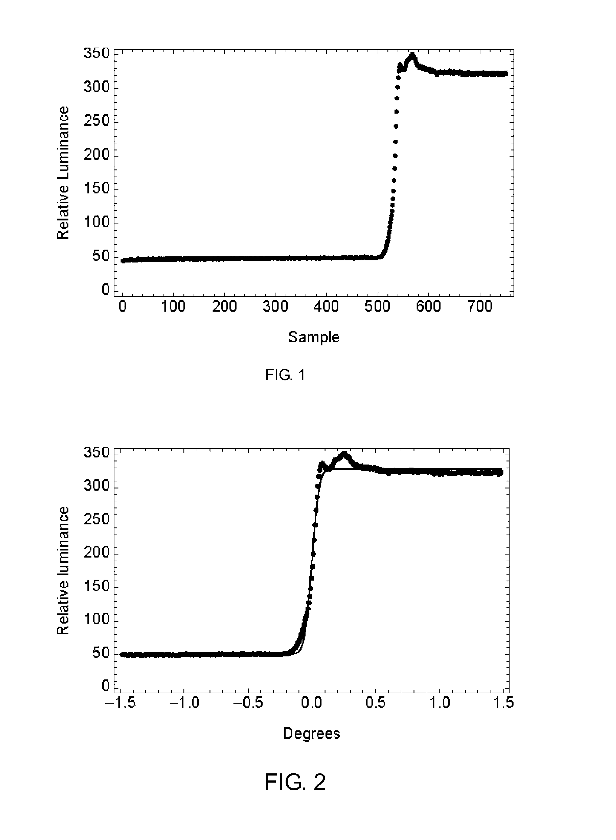
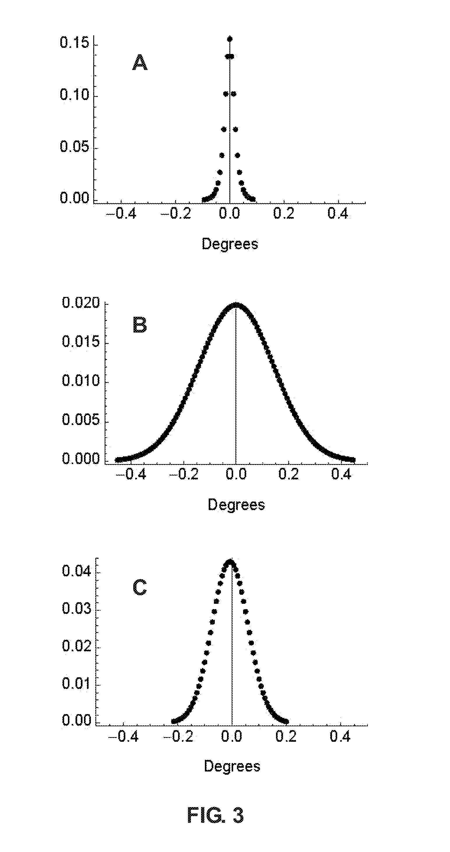
  • Visible motion blur
  • Visible motion blur
  • Visible motion blur

Examples


Embodiment Construction

[0020]Before the present invention is described in detail, it is to be understood that unless otherwise indicated this invention is not limited to specific imaging systems.

[0021]It must be noted that as used herein and in the claims, the singular forms “a,”“and” and “the” include plural referents unless the context clearly dictates otherwise. Thus, for example, reference to “an imaging system” includes two or more imaging systems, and so forth.

[0022]Where a range of values is provided, it is understood that each intervening value, to the tenth of the unit of the lower limit unless the context clearly dictates otherwise, between the upper and lower limit of that range, and any other stated or intervening value in that stated range, is encompassed within the invention. The upper and lower limits of these smaller ranges may independently be included in the smaller ranges, and are also encompassed within the invention, subject to any specifically excluded limit in the stated range. Wher...


PUM


Abstract

A method of measuring motion blur is disclosed comprising obtaining a moving edge temporal profile r1(k) of an image of a high-contrast moving edge, calculating the masked local contrast m1(k) for r1(k) and the masked local contrast m2(k) for an ideal step edge waveform r2(k) with the same amplitude as r1(k), and calculating the measure or motion blur Ψ as a difference function,Ω=S(ΔxΣk|m1(k)−m2(k)|β)1 / β.The masked local contrasts are calculated using a set of convolution kernels scaled to simulate the performance of the human visual system, and Ψ is measured in units of just-noticeable differences.

Description

RELATED APPLICATION[0001]This application claims priority to U.S. Provisional Patent Application No. 61 / 520,357 filed May 24, 2011, which is hereby incorporated by reference.ORIGIN OF THE INVENTION[0002]The invention described herein was made by an employee of the United States Government and may be manufactured and used by or for the Government of the United States of America for governmental purposes without the payment of any royalties thereon or therefor.FIELD OF THE INVENTION[0003]One or more embodiments of the present invention relate to methods for measuring motion blur in imaging systems.BACKGROUND[0004]Motion blur is a significant defect of most current display technologies. Motion blur arises when the display presents individual frames that persist for significant fractions of a frame duration. When the eye smoothly tracks a moving image, the image is smeared across the retina during the frame duration. Although motion blur may be manifest in any moving image, one widely u...

Claims


Application Information

Patent Timeline
Patent Type & Authority Patents(United States)
IPC IPC(8): H04N5/228G06K9/00H04N23/40
CPCH04N5/23267G06T5/003G06T2207/20201H04N5/23254G06K9/00H04N5/228H04N23/6811H04N23/683G06T5/73
Inventor WATSON, ANDREW B.AHUMADA, ALBERT J.
Owner NASA
Learn More