
Device for balancing a transmission network

a transmission network and device technology, applied in the direction of ac network circuit arrangement, process and machine control, instruments, etc., can solve the problem of uneconomical use of converters

Inactive Publication Date: 2014-03-18
ABB POWER GRIDS SWITZERLAND AG
View PDF10 Cites 6 Cited by
  • Summary
  • Abstract
  • Description
  • Claims
  • Application Information

AI Technical Summary

Benefits of technology

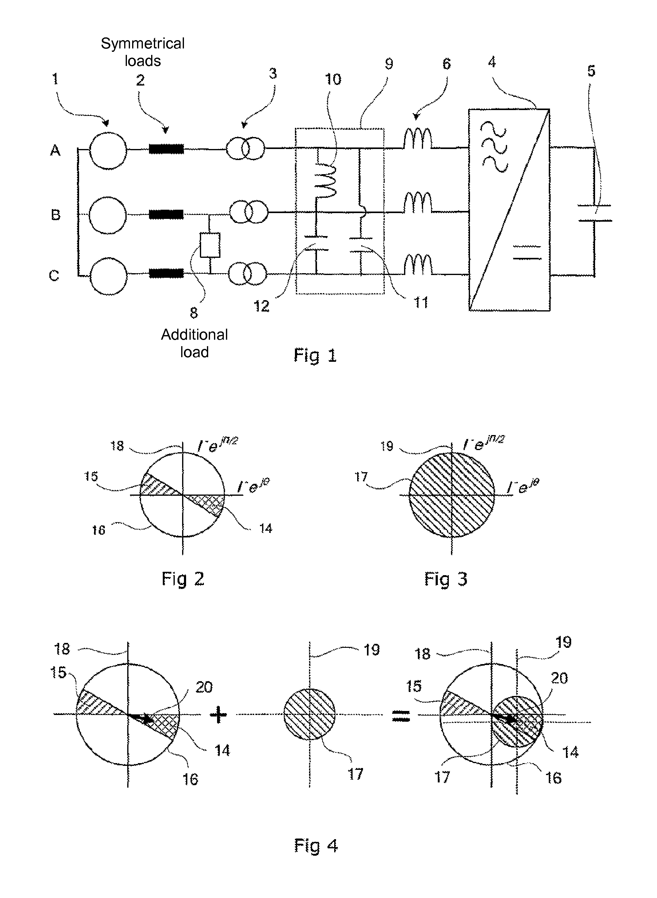
[0008]According to the invention, the object is achieved by connecting to the polyphase network a compensator comprising a voltage-source converter, the working point of which is displaced so that the operating range covers substantially the necessary control range. This results in the advantage that a converter with a smaller operating range may be utilized. Such a displacement of the working point of the converter is achieved by causing the compensator to comprise a balancing device including reactive and capacitive elements connected between the phases in the network. These elements together form an offset bank for the negative-sequence current.
[0010]By supplementing the converter with a balancing device comprising inductors and capacitors, the working point of the converter is displaced. A displacement of the working point corresponding to about half of the maximum balancing requirement permits the operating range of the converter to be reduced and its rated power to be halved. A balancing device comprising an offset bank consisting of discrete components containing inductors and capacitors connected between the phases creates a negative-sequence current with a fixed amplitude and direction.

Problems solved by technology

If this sector is smaller than a quadrant, it is uneconomical to use a converter, the operating range of which comprises the whole circle.

Method used


Image

  • Device for balancing a transmission network
  • Device for balancing a transmission network
  • Device for balancing a transmission network

Examples


Embodiment Construction

[0021]FIG. 1 shows an ac voltage network 1 with three phases A, B and C with substantially symmetrical loads 2. Between the second phase B and the third phase C, an additional load 8 is unsymmetrically connected. The load 8 is only symbolically indicated and may include both resistive and inductive components. A compensation installation comprising a voltage-source converter 4 with a capacitor bank 5, reactors 6 and a balancing device 9 is connected to the ac voltage network by way of a transformer 3. The balancing device comprises an inductance 10 connected between the first phase A and the second phase B, and a capacitance connected between the first phase A and the third phase C. In the example shown, the balancing device also comprises a capacitance 12 connected in parallel with the load.

[0022]FIG. 2 shows, in a coordinate system 18, that range within which the negative-sequence current normally lies for a load connected between two phases. The load range 15 constitutes a circul...


PUM


Abstract

A compensator for balancing an ac voltage network with a load connected between two phases. The compensator includes a voltage-source converter and a balancing device. The balancing device includes an inductance connected between phases before the load.

Description

CROSS-REFERENCE TO RELATED APPLICATIONS[0001]This application is the national phase under 35 U.S.C. §371 of PCT / SE2005 / 002069 filed Dec. 30, 2005.TECHNICAL FIELD[0002]The present invention relates to a device for power compensation of an ac voltage network with an uneven load. Such a device is known under the acronym FACTS (Flexible AC Transmission System). In particular, the invention relates to a device for balancing a transmission network with a plurality of phases and with a load between two phases only. The load is usually both resistive and inductive, such as, for example, an electrically rotating machine connected to the network via a converter.BACKGROUND ART[0003]It is known that the transmission power of an ac voltage network is reduced during reactive load and during uneven load of the three phases. Usually, the load is reactive and symmetrical. In this context, it is known to arrange a compensator comprising capacitors connectable to the network. It is also known to conne...

Claims


Application Information

Patent Timeline
Patent Type & Authority Patents(United States)
IPC IPC(8): G05F1/70
CPCY02E40/12H02J3/1864Y02E40/10
Inventor THORVALDSSON, BJORN
Owner ABB POWER GRIDS SWITZERLAND AG
Learn More