
Developing cartridge and process cartridge with grip portion of sealing member preventing mounting of cartridge

a technology of sealing member and cartridge, which is applied in the direction of electrographic process equipment, instruments, optics, etc., can solve the problems of inability to control the attitude of the sealing grip member in a packed state, difficulty in retaining the bent state, and increase in transportation costs

Inactive Publication Date: 2014-03-11
CANON KK
View PDF57 Cites 25 Cited by
  • Summary
  • Abstract
  • Description
  • Claims
  • Application Information

AI Technical Summary

Benefits of technology

The invention is about a developing cartridge and a process cartridge that make it easy to know if the seal member is not removed. The seal member is attached to the end of the cartridge and a grip member is fixed inside the full length of the cartridge. This grip portion prevents the developing cartridge from being mounted in the image forming apparatus. The technical effect of this invention is to ensure the seal member is always in place and the cartridge can be easily identified.

Problems solved by technology

However, in JP-A 2002-278417, the full length of the cartridge becomes long and the presence of the seal grip member causes an increase in size of an individual packaging box for packing the cartridge at the time of shipment, thus being directly linked to an increase in transportation cost.
However, even in that case, it is difficult to retain the bent state during the packing in a manufacturing process and further an attitude of the seal grip member in a packed state cannot be controlled.
For this reason, there was a possibility that detachment of the seal grip member from a container, deformation of the seal grip member, and the like are caused.
At that time, there is a possibility that visibility of the seal grip member becomes poor, so that there is a possibility that the cartridge is mounted in the image forming apparatus without removing the toner seal member.
For that reason, even in the case where the toner seal member is not removed, there is a need to cause the cartridge to interfere with the main assembly of the image forming apparatus to prevent the mounting of the cartridge.

Method used


Image

  • Developing cartridge and process cartridge with grip portion of sealing member preventing mounting of cartridge
  • Developing cartridge and process cartridge with grip portion of sealing member preventing mounting of cartridge
  • Developing cartridge and process cartridge with grip portion of sealing member preventing mounting of cartridge

Examples


first embodiment

[First Embodiment]

(General structure of color electrophotographic image forming apparatus)

[0036]First, a constitution and an image forming operation of the color electrophotographic image forming apparatus in which the developing cartridges are mounted and an image is formed will be described.

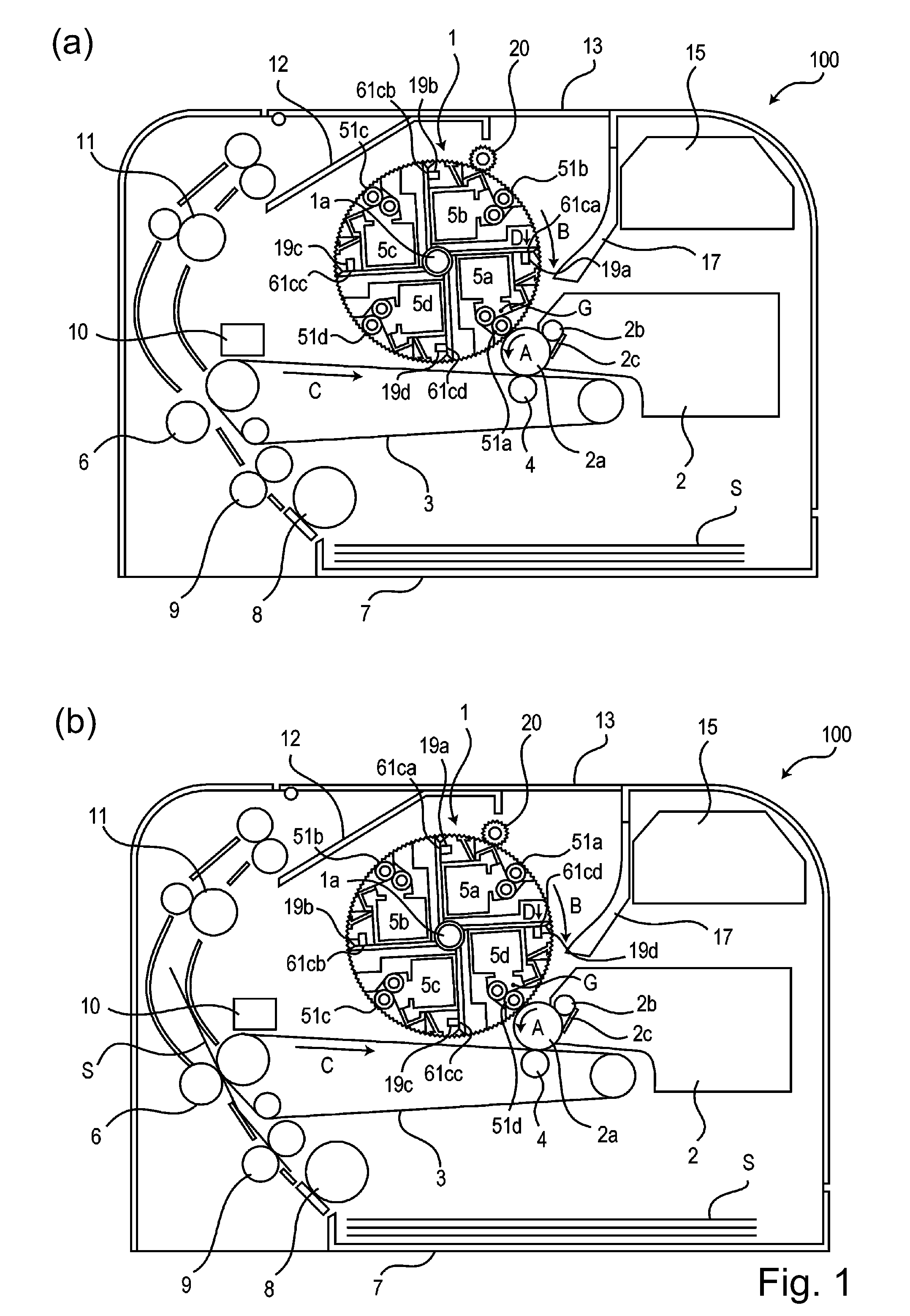
[0037]The color electrophotographic image forming apparatus in this embodiment of the present invention is a four color-based full-color laser beam printer. FIG. 1(a) is a sectional view showing a schematic structure of the image forming apparatus during a developing operation of a yellow developing cartridge 5a. FIG. 1(b) is a sectional view showing a schematic structure of the image forming apparatus during the developing operation of a black developing cartridge 5d.

[0038]As shown in FIG. 1(a), an image forming apparatus 100 includes a photosensitive drum 2a. At a periphery of the photosensitive drum 2a, a charging means 2b (charging roller in this embodiment) for uniformly charging the phot...


PUM


Abstract

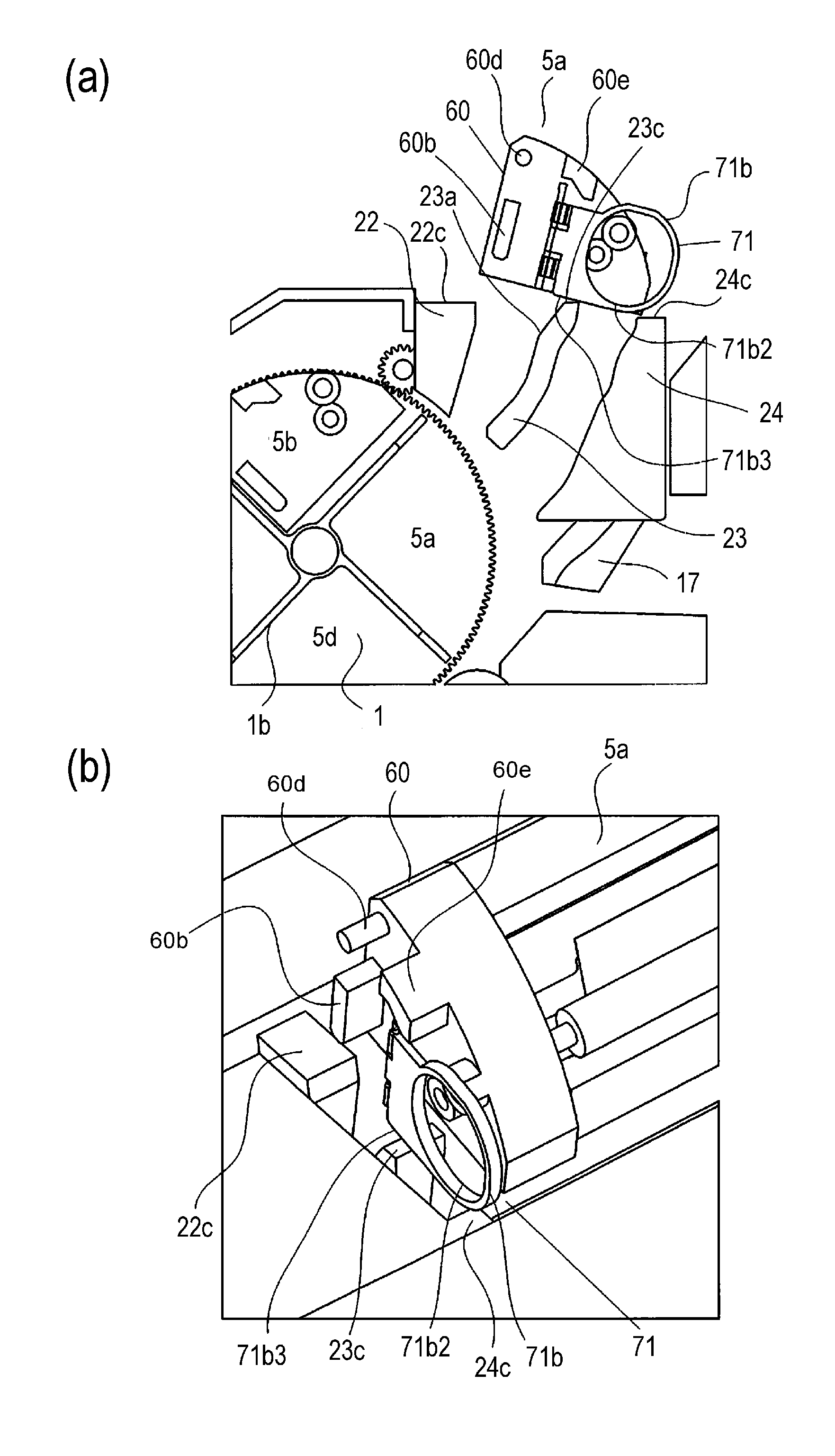
A developing cartridge is detachably mountable to a main assembly of an image forming apparatus by passing through a mounting guide provided in the main assembly. The developing cartridge includes a frame; a developer carrying member for carrying a developer for developing an electrostatic latent image; a portion to be guided for being guided by the mounting guide when the developing cartridge passes through the mounting guide; an accommodating portion for accommodating the developer; a seal member for unsealably sealing an opening for permitting supply of the developer from the accommodating portion to the developer carrying member; and a grip member, provided at a longitudinal end portion of the seal member, including a fixed portion dismountably fixed on the frame and a grip portion to be gripped when the seal member is removed. The grip portion is disposed in a state in which the grip portion is bent relative to the fixed portion in a direction crossing a mounting direction of the developing cartridge. The grip portion prevents mounting of the developing cartridge by contacting a part of the image forming apparatus when the developing cartridge is mounted in the main assembly of the image forming apparatus.

Description

FIELD OF THE INVENTION AND RELATED ART[0001]The present invention relates to a developing cartridge and a process cartridge which are detachably mountable to an electrophotographic image forming apparatus.[0002]Here, the electrophotographic image forming apparatus forms an image on a recording material (medium) by using an electrophotographic image forming process. For example, the image forming apparatus includes an electrophotographic copying machine, an electrophotographic printer (such as an LED printer or a laser beam printer), an electrophotographic facsimile machine, an electrophotographic word processor, and the like.[0003]The developing cartridge integrally holds, as process means actable on an electrophotographic photosensitive member, at least a developing means and is to be mounted into and demounted from a main assembly of the electrophotographic image forming apparatus.[0004]Further, the developing cartridge can be mounted into and demounted from the apparatus main ass...

Claims


Application Information

Patent Timeline
Patent Type & Authority Patents(United States)
IPC IPC(8): G03G15/08
CPCG03G15/0841G03G15/0839G03G2215/0177G03G15/0896G03G15/0877G03G15/0882
Inventor UENO, TAKAHITONUMATA, TETSUYA
Owner CANON KK
Learn More