
Coherent optical receiving apparatus and optical signal processing method

a receiving apparatus and optical signal technology, applied in coherence multiplexing, polarisation multiplexing, multi-component communication, etc., can solve the problems of phase distortion, phase distortion of phase-modulated signals, and different ideal rz pulse carver optical pulses, etc., to achieve accurate estimation and stable performance

Inactive Publication Date: 2014-03-11
ELECTRONICS & TELECOMM RES INST
View PDF20 Cites 6 Cited by
  • Summary
  • Abstract
  • Description
  • Claims
  • Application Information

AI Technical Summary

Benefits of technology

Accurately estimates and compensates for frequency offsets and phase distortions, providing stable performance by separating and correcting distortions in both even-numbered and odd-numbered samples, thereby improving the accuracy of frequency offset estimation and reducing OSNR penalties.

Problems solved by technology

However, an actually used RZ pulse carver is different from an ideal RZ pulse carver.
Therefore, a phase distortion may occur in an optical pulse generated by the RZ pulse carver.
The phase distortion may deteriorate a performance of a phase-modulated signal.
The phase distortion may cause an error in estimating a frequency offset that is a difference in frequency between a laser used by a transmitting apparatus and a laser used by a receiving apparatus.

Method used


Image

  • Coherent optical receiving apparatus and optical signal processing method
  • Coherent optical receiving apparatus and optical signal processing method
  • Coherent optical receiving apparatus and optical signal processing method

Examples


Embodiment Construction

[0036]Reference will now be made in detail to embodiments of the present invention, examples of which are illustrated in the accompanying drawings, wherein like reference numerals refer to the like elements throughout. Embodiments are described below to explain the present invention by referring to the figures.

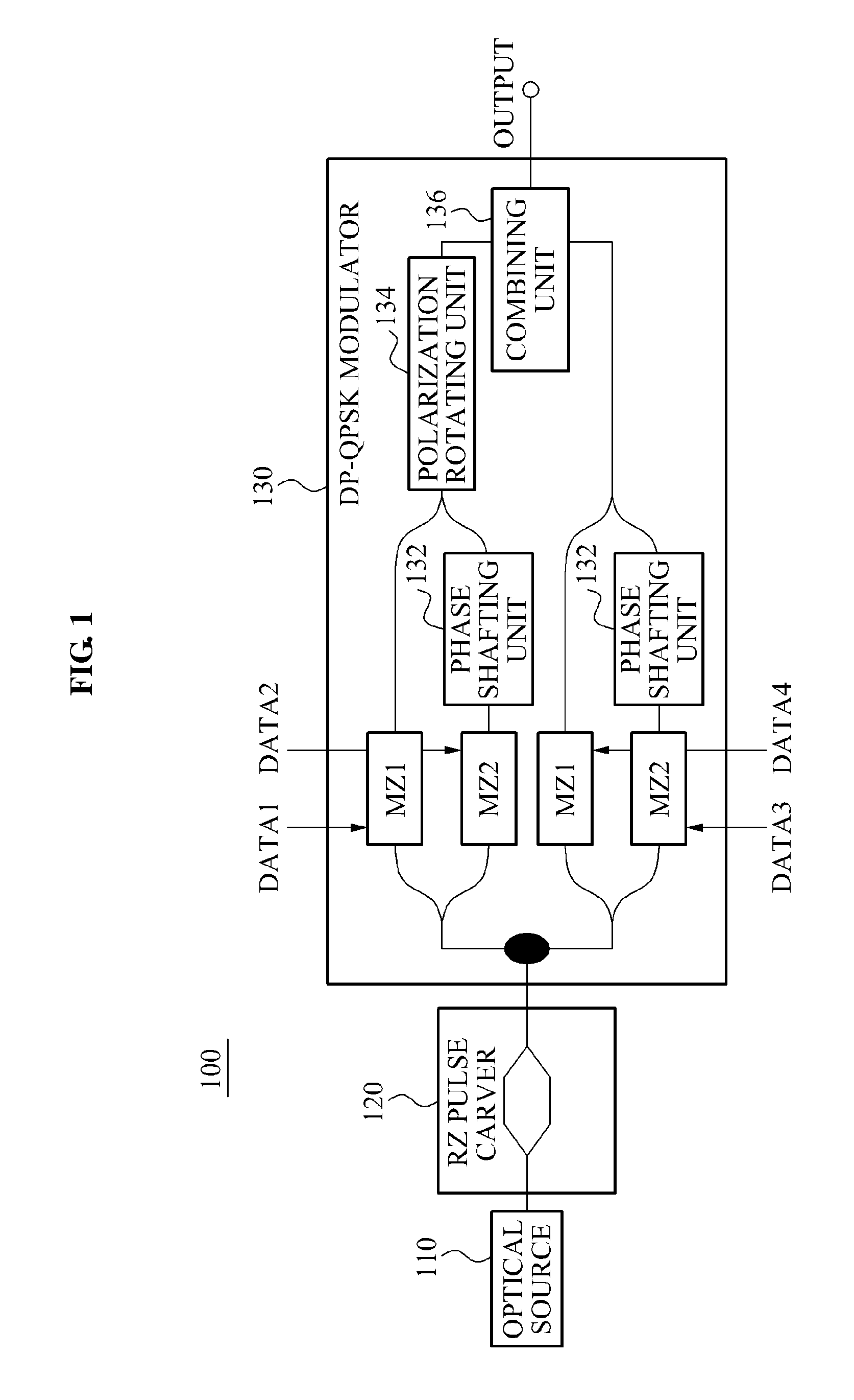
[0037]FIG. 1 illustrates a dual polarization quadrature phase shift keying (DP-QPSK) optical transmitting apparatus 100 that utilizes two polarized lights according to an embodiment of the present invention.

[0038]Referring to FIG. 1, the DP-QPSK optical transmitting apparatus 100 may modulate a phase of an optical signal to transmit information. The above described scheme may perform relatively long distance transmission compared with an On-Off keying scheme that modulates an intensity of the optical signal. The DP-QPSK optical transmitting apparatus 100 may use a Mach-Zehnder (MZ) modulator to modulate the phase of the optical signal based on an inputted electric data, and ma...


PUM


Abstract

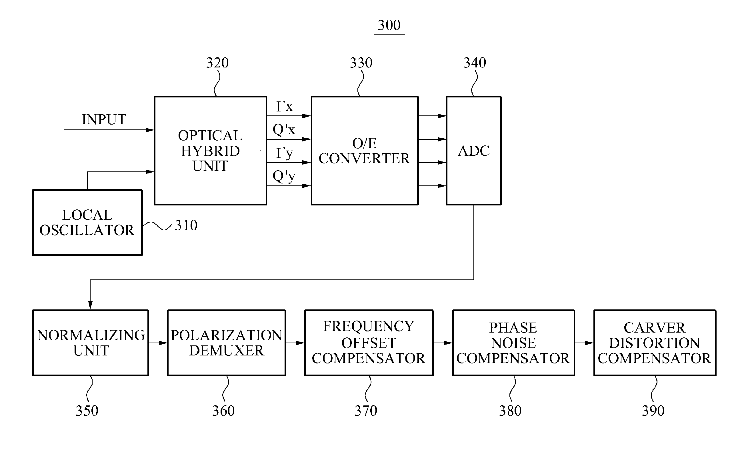
Provided is a coherent optical receiving apparatus and an optical signal processing method. The coherent optical receiving apparatus may include an optical hybrid unit to generate an optical signal by combining a first optical signal inputted from an optical transmitting apparatus and a second optical signal inputted from a local oscillator, a polarization demuxer to demultiplex the optical signal outputted from the optical hybridizing unit, a frequency offset compensator to estimate a frequency offset of at least one of even-numbered samples and odd-numbered samples, and to compensate for a frequency offset of the even-numbered samples and a frequency offset of the odd-numbered samples using the at least one estimated frequency offset, and a carver distortion compensator to compensate for phase distortions of the samples for which the compensation for the frequency offset is performed, the phase distortions being generated by the optical transmitting apparatus.

Description

CROSS-REFERENCE TO RELATED APPLICATION[0001]This application claims the benefit of Korean Patent Application No. 10-2010-0091527, filed on Sep. 17, 2010, in the Korean Intellectual Property Office, the disclosure of which is incorporated herein by reference.BACKGROUND[0002]1. Field of the Invention[0003]The present invention relates to a coherent optical receiving apparatus and an optical signal processing method, and more particularly, to a coherent optical receiving apparatus and an optical signal processing method that accurately estimates a frequency offset to compensate for a phase distortion of the optical signal.[0004]2. Description of the Related Art[0005]A return-to-zero (RZ) pulse carver may be included in a transmitting apparatus to be used for optical transmission. The RZ pulse carver may be configured using a Mach-Zehnder (MZ) optical modulator, to convert a waveform to a RZ pulse. When an intensity of a provided sine-wave is the same as a voltage required by the RZ pul...

Claims


Application Information

Patent Timeline
Patent Type & Authority Patents(United States)
CPCH04J14/002H04B10/616H04B10/614
Inventor CHUNG, HWAN SEOKCHANG, SUN HYOK
Owner ELECTRONICS & TELECOMM RES INST
Learn More