
Power supply controller

a power supply controller and controller technology, applied in the direction of motor/generator/converter stopper, dynamo-electric converter control, electric devices, etc., can solve the problems of inability to control the charging/discharging of the secondary power supply apparatus in a satisfactory manner, and the service life of the secondary power supply apparatus cannot be satisfactorily extended, so as to achieve accurate detection and extend the service life of the secondary power supply apparatus

Inactive Publication Date: 2014-03-11
TOYOTA JIDOSHA KK
View PDF26 Cites 6 Cited by
  • Summary
  • Abstract
  • Description
  • Claims
  • Application Information

AI Technical Summary

Benefits of technology

[0007]Either the stepped-up voltage of the step-up circuit or the power supply voltage (output voltage) of the secondary power supply apparatus is automatically selected to be supplied to the drive circuit in accordance with the balance between the stepped-up voltage and the power supply voltage (the relation of the magnitudes of the voltages). Therefore, in the present invention, the charge / discharge control means controls the charging / discharging of the secondary power supply apparatus by controlling the stepped-up voltage of the step-up circuit. In this case, the charge / discharge control means controls the stepped-up voltage of the step-up circuit on the basis of the charged amount of the secondary power supply apparatus detected by the charged amount detection means and the target charged amount. Accordingly, the charging and discharging of the secondary power supply apparatus can be properly switched, whereby a good charged state of the secondary power supply apparatus can be maintained. Notably, the target charged amount may be a previously determined fixed value or a value which is changed in accordance with the conditions of use, etc.
[0045]In this invention, the charge / discharge current cumulating means obtains a cumulative value of a charge / discharge current flowing to or from the secondary power supply apparatus during a period in which the ignition switch is on, and the charged amount of the secondary power supply apparatus is detected on the basis of the cumulative value. When the vehicle is not used for a long period of time, the charged amount of the secondary power supply apparatus changes due to natural discharge or the like. In view of this, in the present invention, when the ignition switch is turned off, the end-time discharge means discharges the electric charge of the secondary power supply apparatus to the primary power supply apparatus. Accordingly, the initial charged amount at the time when the cumulation of the charge / discharge current is started is less likely to vary, whereby the charged amount can be detected accurately. Further, since the electric charge is discharged when the vehicle is not used, when the secondary power supply apparatus is composed of a capacitor, the service life of the secondary power supply apparatus can be extended.

Problems solved by technology

Although the apparatus proposed in Japanese Patent Application Laid-Open No. 2007-91122 is configured to selectively perform the charging of electricity from the primary power supply apparatus to the secondary power supply apparatus or the supply of electricity from the secondary power supply apparatus to the motor drive circuit through operation of the switches, the apparatus cannot control the charging / discharging of the secondary power supply apparatus in a satisfactory manner.
As a result, the secondary power supply apparatus cannot be maintained in a satisfactorily charged state.

Method used


Image

  • Power supply controller
  • Power supply controller
  • Power supply controller

Examples


Embodiment Construction

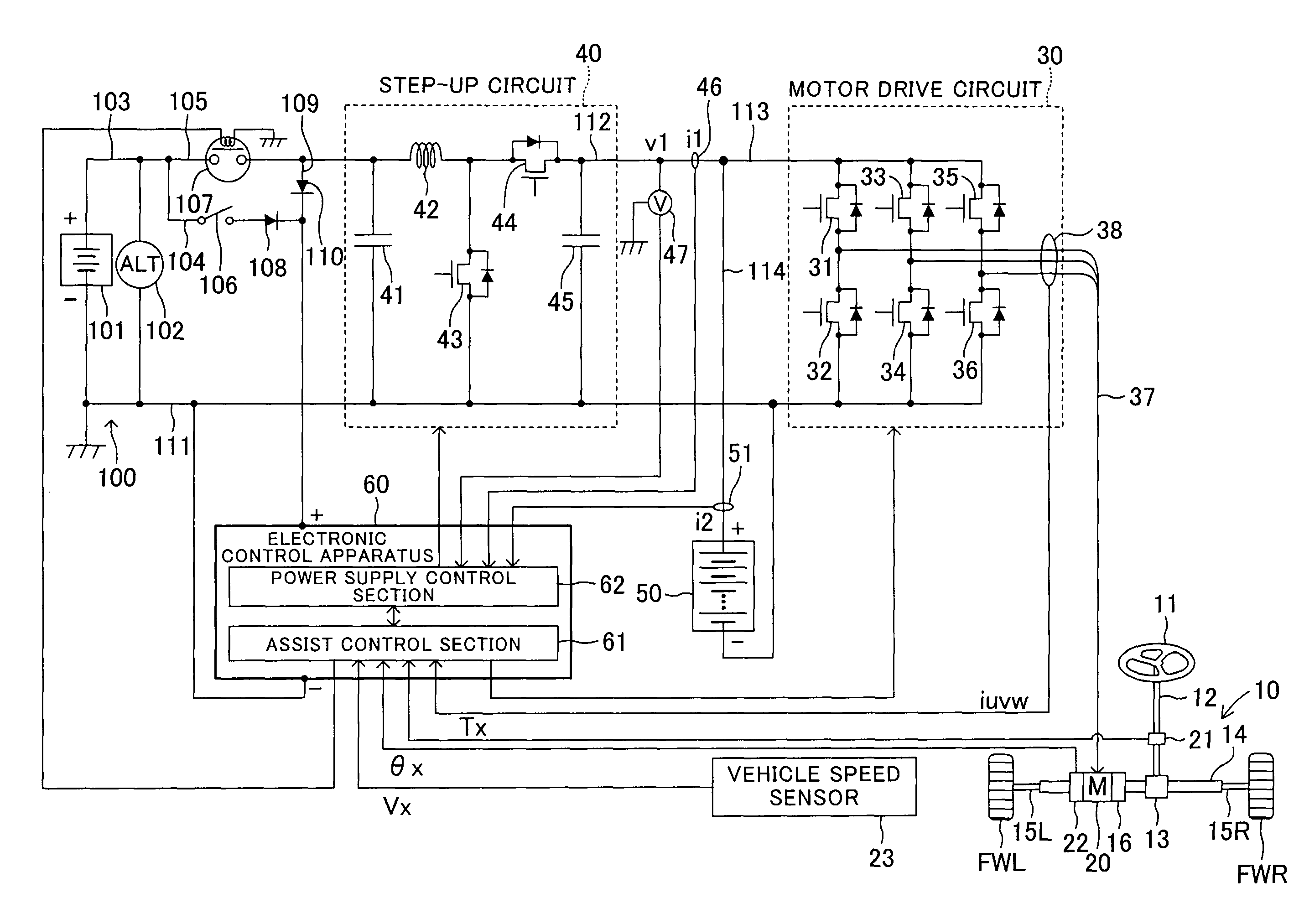
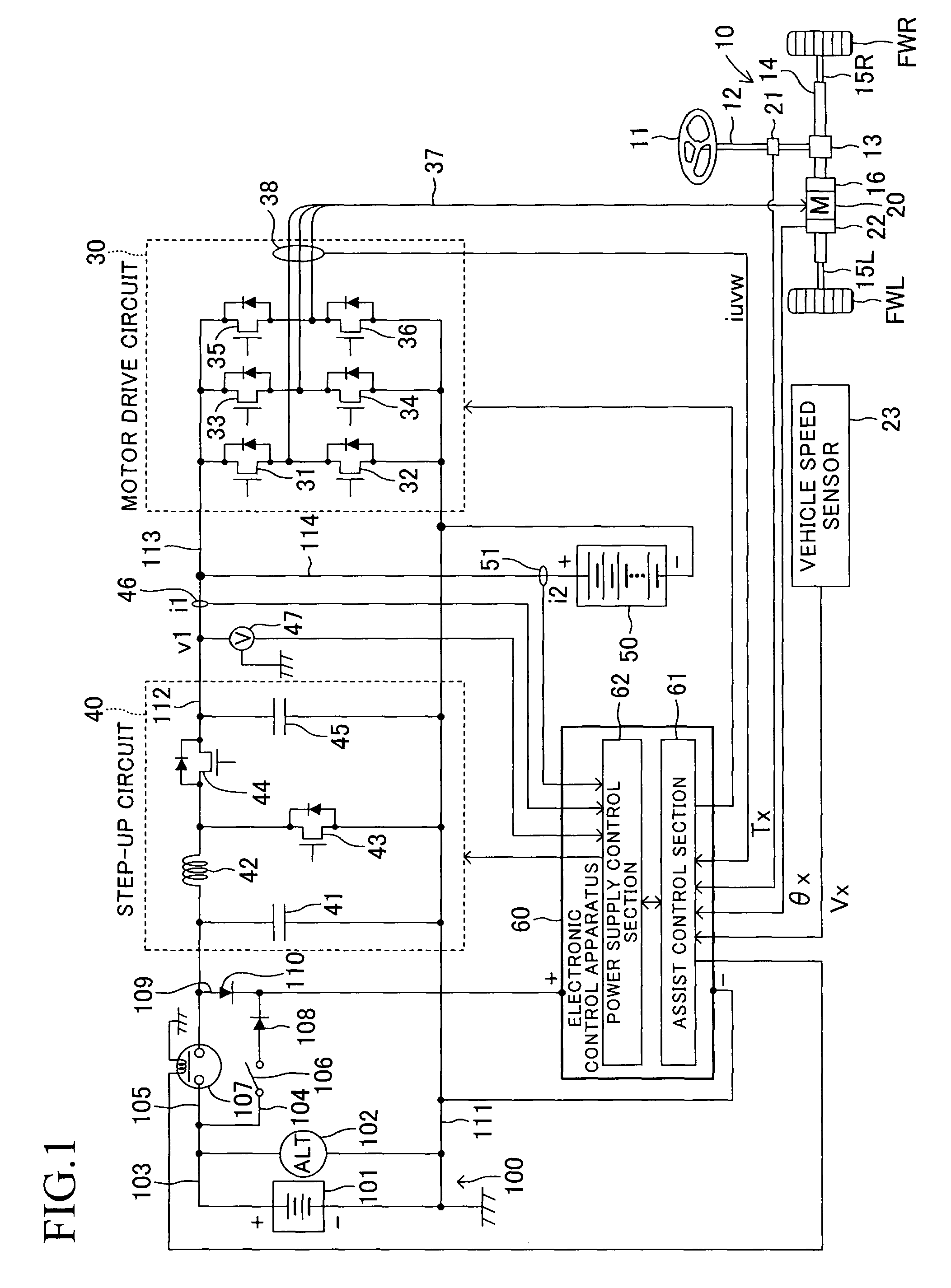
[0057]A power supply control apparatus according to one embodiment of the invention will now be described with reference to the drawings. FIG. 1 schematically shows the configuration of an electric power steering apparatus for a vehicle equipped with a power supply control apparatus according to the embodiment.

[0058]The electric power steering apparatus for a vehicle according to the embodiment is mainly composed of a steering mechanism 10 which steers steerable wheels in accordance with steering operation of a steering wheel 11; an electric motor 20 incorporated in the steering mechanism 10 and adapted to generate steering assist torque; a motor drive circuit 30 for driving the electric motor 20; a step-up circuit 40 which steps up an output voltage of a primary power supply apparatus 100 and supplies the stepped-up voltage to the motor drive circuit 30; a secondary power supply apparatus 50 connected in parallel with a power supply circuit extending between the step-up circuit 40 ...


PUM


Abstract

A power supply control section calculates a target charge / discharge current of a secondary power supply apparatus based on an actual charged amount and a target charged amount of the secondary power supply apparatus, and feedback-controls the stepped-up voltage of a step-up circuit such that an actual charge / discharge current detected by a secondary current sensor coincides with a target charge / discharge current. When the actual charged amount (1) is equal to or greater than the target charged amount, the target charge / discharge current is set to zero to prevent overcharging, and (2) is less than the target charged amount, a target charge current corresponding to a capacity margin of the step-up circuit is set to quickly charge the secondary power supply apparatus. When the output of the step-up circuit has no margin, the target charge / discharge current is set to zero.

Description

TECHNICAL FIELD[0001]The present invention relates to a power supply control apparatus which includes a primary power supply apparatus and a secondary power supply apparatus for supplying electric power to an electric actuator.BACKGROUND ART[0002]Conventionally, for example, an electric power steering apparatus includes an electric motor for imparting a steering assist torque to a rotating operation of a steering wheel, and adjusts the steering assist torque through performance of energization control which changes the current supplied to the electric motor. Such an electric power steering apparatus, which uses an onboard battery as a power source, consumes a large mount of electric power. Therefore, an apparatus proposed in Japanese Patent Application Laid-Open (kokai) No. 2007-91122 includes a secondary power supply apparatus for supplementing the onboard battery. The secondary power supply apparatus is connected in parallel with a power supply line extending from the onboard batt...

Claims


Application Information

Patent Timeline
Patent Type & Authority Patents(United States)
IPC IPC(8): B60L1/00
CPCH02J7/0054B62D5/046B62D5/0457B62D5/0481Y10T307/68H02J7/342B60R16/033B62D5/04B62D6/00
Inventor YAMASHITA, MASAHARU
Owner TOYOTA JIDOSHA KK
Learn More