Valve control apparatus for internal combustion engine

a valve control and internal combustion engine technology, applied in mechanical equipment, valve arrangements, machines/engines, etc., can solve the problems of unable to attach the rocker arm to the control shaft from an axial direction of the control shaft, etc., to achieve the effect of increasing the weight (inertia mass) of the whole worsening the operating performance of the rocker arm

Inactive Publication Date: 2014-03-11
HITACHI AUTOMOTIVE SYST LTD
View PDF10 Cites 3 Cited by
  • Summary
  • Abstract
  • Description
  • Claims
  • Application Information

AI Technical Summary

Benefits of technology

[0004]However, in the technique disclosed in the above Application, since the control shaft is formed integrally in the crank shape, the rocker arm cannot be attached to the control shaft from an axial direction of the control shaft. Hence, a base end portion of the rocker arm is formed as pieces divided in a radial direction of the control shaft, and the divided pieces are firmly connected with each other by bolts at the time of assembly. Accordingly, a weight (inertia mass) of whole of the rocker arm is increased, and thereby, there is a risk that an operating performance of the rocker arm is worsened at the time of high-speed operation.

Problems solved by technology

However, in the technique disclosed in the above Application, since the control shaft is formed integrally in the crank shape, the rocker arm cannot be attached to the control shaft from an axial direction of the control shaft.
Accordingly, a weight (inertia mass) of whole of the rocker arm is increased, and thereby, there is a risk that an operating performance of the rocker arm is worsened at the time of high-speed operation.

Method used


Image

  • Valve control apparatus for internal combustion engine
  • Valve control apparatus for internal combustion engine
  • Valve control apparatus for internal combustion engine

Examples


first embodiment

[0021][First Embodiment]

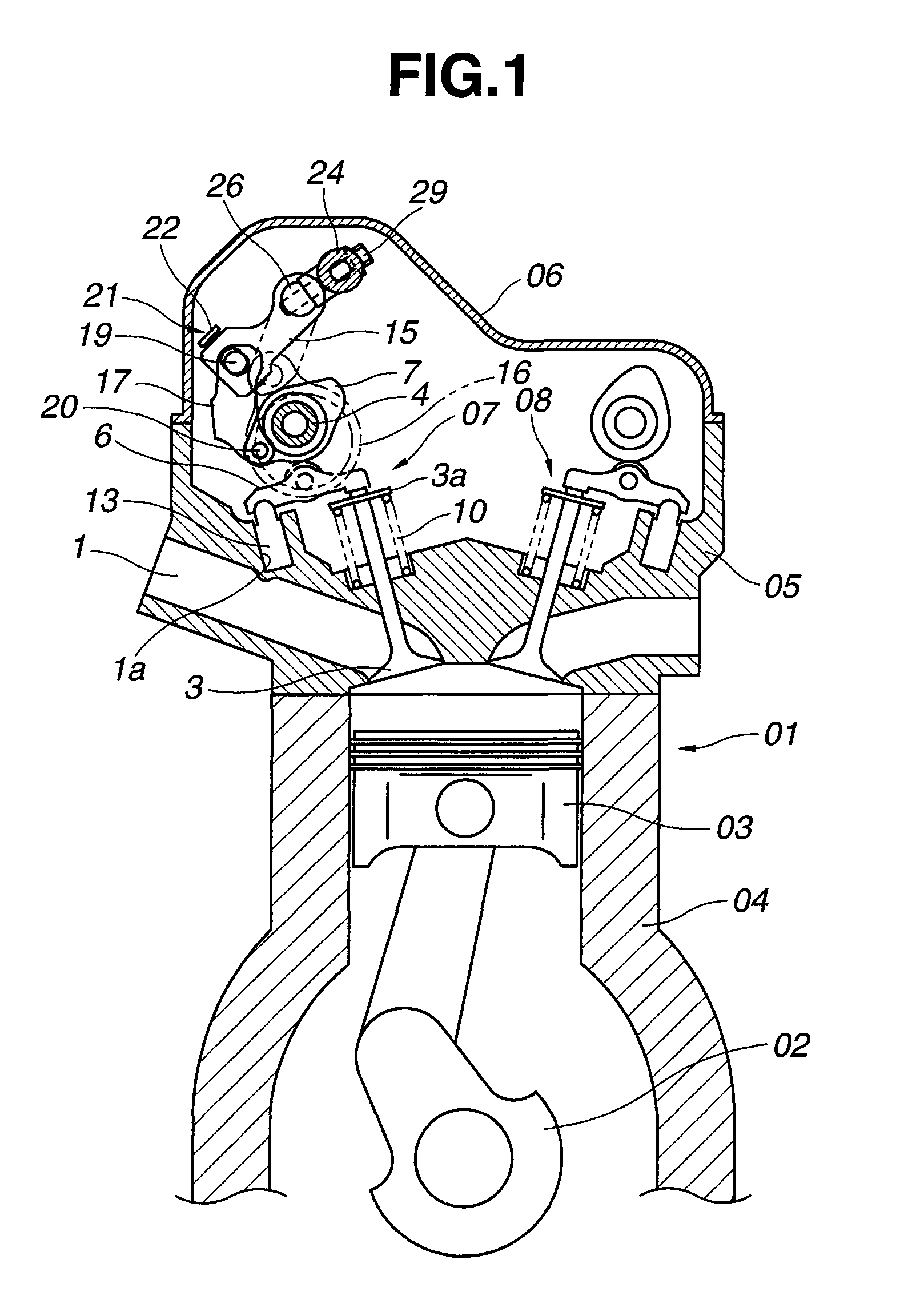
[0022]As shown in FIG. 1, an internal combustion engine 01 includes a cylinder block 04, a cylinder head 05, an intake-side valve control apparatus 07, and an exhaust-side valve control apparatus 08. The cylinder block 04 accommodates and rotatably receives a crankshaft 02 therein, and slidably receives a piston 03 in a cylinder bore. The cylinder head 05 is provided on the cylinder block 04 and fixed to an upper end of the cylinder block 04. An upper end of the cylinder head 05 is covered or enclosed by a head cover 06. The intake-side valve control apparatus 07 and the exhaust-side valve control apparatus 08 are provided at an upper end portion of the cylinder head 05, every cylinder. The intake-side valve control apparatus 07 includes a variable mechanism for varying a valve lift-amount characteristic and a working angle (angle range of valve-open period) of an intake valve 3 in accordance with an operating state of the engine.

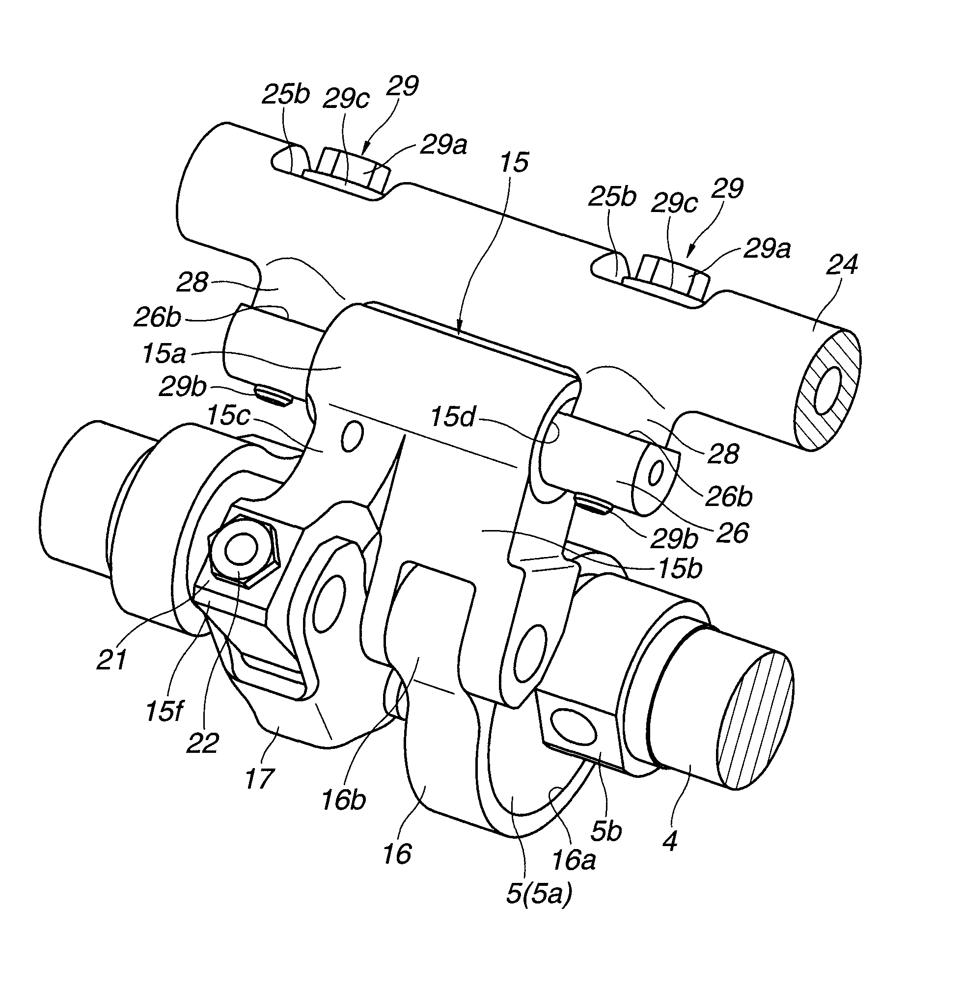
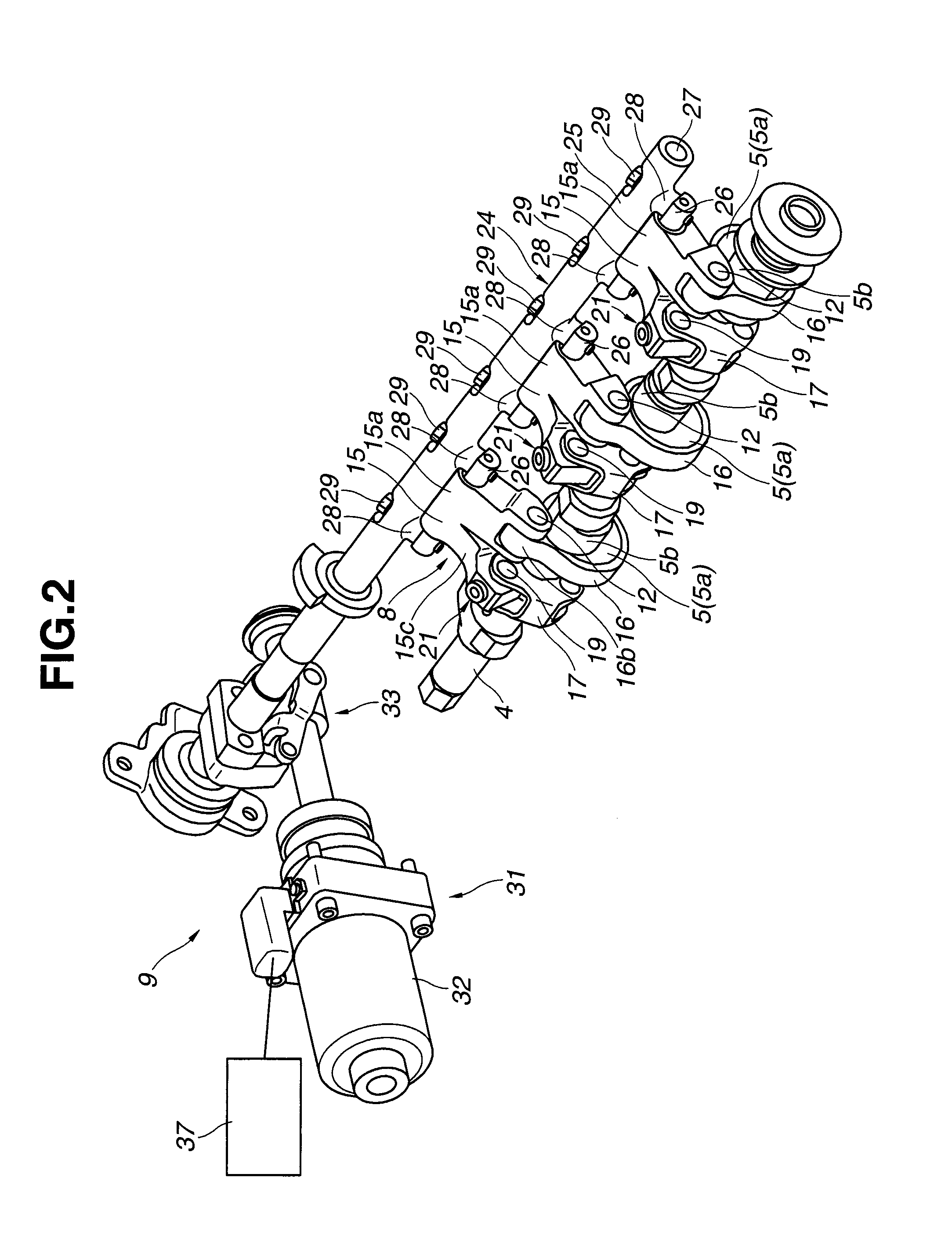
[0023]As shown in FIGS. 1-3 a...

second embodiment

[0077][Second Embodiment]

[0078]FIG. 8 is a cross sectional view showing a structure according to a second embodiment of the present invention. A basic structure according to the second embodiment is approximately same as that of the first embodiment. As a structure different from the first embodiment, a pair of boss portions 38 and 38 are provided, instead of the pair of first cutout surfaces 25b and 25b of control shaft main body 25 of the first embodiment. Structural elements in the second embodiment which are common to the first embodiment are given the same reference signs as the first embodiment, and concrete explanations thereof will be omitted for the purpose of simplification of the disclosure.

[0079]The both boss portions 38 and 38 are located on an radially opposite side of the control shaft main body 25 from the protruding portions 28 and 28, namely are provided along diameter lines of control shaft main body 25 which pass through the protruding portions 28 and 28. That is...

third embodiment

[0083][Third Embodiment]

[0084]FIG. 9 is a cross sectional view showing a structure according to a third embodiment of the present invention. In the third embodiment, the pair of bolts 29 and 29 are inserted into and fixed to the control shaft main body 25 from a side of the control eccentric shaft 26.

[0085]The pair of boss portions 38 and 38 are provided to the control shaft main body 25 in the same manner as the second embodiment. A female threaded hole 38b is formed in each boss portion 38 and in a portion of the control shaft main body 25 which is located on the boss portion 38, in an axial direction of the boss portion 38 (i.e., perpendicularly to the axial direction of control shaft main body 25). Each female threaded hole 38b is formed to be continuous with the bolt insertion hole 25a, and passes completely through the boss portion 38. This female threaded hole 38b functions as a fixing hole for the bolt 29. Moreover, the bolt insertion hole 25a is formed in each protruding po...


PUM


Abstract

A valve control apparatus includes a drive shaft; a control shaft including a control shaft main body configured to be rotationally controlled according to a state of engine, and a control eccentric shaft located eccentrically relative to a rotation center of the control shaft main body; a rocker arm swingably supported by the control eccentric shaft and configured to convert a rotational motion of the drive shaft to a swinging motion; and a swing cam configured to open / close an engine valve according to the swinging motion of rocker arm. Both ends of the control eccentric shaft are formed with fixing holes extending in a radial direction of the control eccentric shaft. The control shaft main body is formed with insertion holes passing through the control shaft main body in a radial direction of the control shaft main body. The insertion holes respectively face the fixing holes. The control eccentric shaft is fixed to the control shaft main body by bolts. The bolts pass respectively through the pair of insertion holes and are screwed respectively into the fixing holes.

Description

BACKGROUND OF THE INVENTION[0001]The present invention relates to a valve control apparatus for an internal combustion engine, which is able to vary a lift-amount characteristic, a working angle (valve-open period) or the like of an intake valve or an exhaust valve functioning as an engine valve, in accordance with an operating state of the engine.[0002]In the field of a valve control apparatus functioning to vary a valve lift amount or working angle of the engine valve through a rocker arm by controlling a rotation of control shaft, it is required that an operational control range of the valve lift amount or the like of the engine valve is enlarged by widely varying a swing fulcrum of the rocker arm.[0003]United States Patent Application Publication No. 2009 / 0050086 (corresponding to Japanese Patent Application Publication No. 2009-47083) discloses a previously-proposed valve control apparatus. In this technique, the control shaft is integrally formed in a crank shape in order to s...

Claims


Application Information

Patent Timeline
Patent Type & Authority Patents(United States)
IPC IPC(8): F01L1/34
CPCF01L1/053F01L13/0026F01L13/0021F01L2013/0073F01L2820/032
Inventor KAJIURA, MIKIHIROYAMADA, YOSHIHIKO
Owner HITACHI AUTOMOTIVE SYST LTD
Why Eureka
Try Eureka