Method and system for providing reliable communication with redundancy for energy constrained wireless systems

a wireless network and network node technology, applied in the direction of frequency-division multiplex, testing/monitoring control systems, instruments, etc., can solve the problems of inability to determine the status of the devices supervised by the malfunctioning device, redundancy may require additional resources and/or complexity, and communication may be resource-intensive, etc., to achieve the effect of improving the efficiency of network supervision

Active Publication Date: 2014-03-04
ROBERT BOSCH GMBH
View PDF22 Cites 2 Cited by
  • Summary
  • Abstract
  • Description
  • Claims
  • Application Information

AI Technical Summary

Problems solved by technology

Since communication may be resource expensive, each device may be supervised by only one other device.
However, if this other device malfunctions, then it may be difficult to determine the status of the devices that are supervised by the malfunctioning device.
This problem may be handled, for example, by having redundancy, but such redundancy may require additional resources and / or complexity.
In certain wireless communication systems, transmitting is more energy expensive than receiving, or in other words, transmitting is more “energy hungry” than receiving, that is, on average it may require more energy to transmit messages than to receive messages.

Method used


Image

  • Method and system for providing reliable communication with redundancy for energy constrained wireless systems
  • Method and system for providing reliable communication with redundancy for energy constrained wireless systems
  • Method and system for providing reliable communication with redundancy for energy constrained wireless systems

Examples


Embodiment Construction

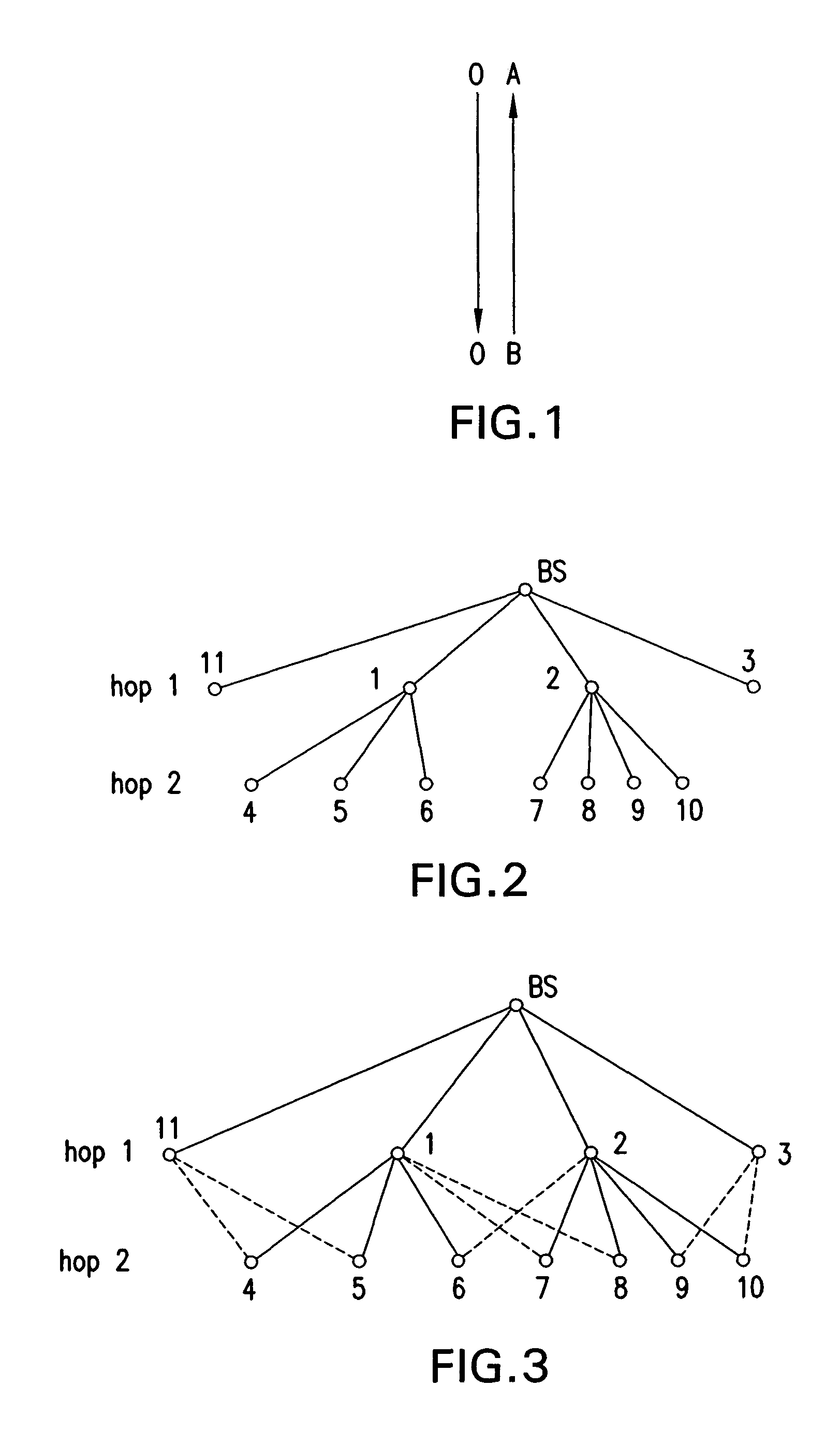
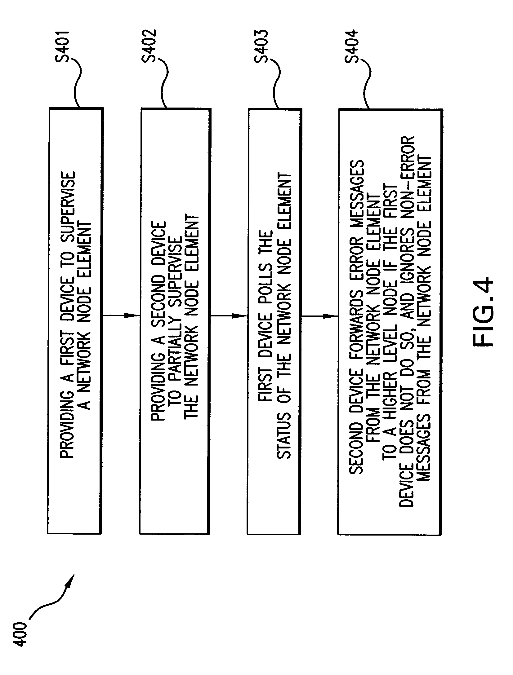
[0031]FIG. 1 shows exemplary network node elements A and B of a wireless network, in which network node element A supervises network node element B. In this regard, to supervise network node element B, network node element A may periodically poll network node element B and receive an acknowledgement with the status of network node element B. If network node element A and network node element B are part of a multihop system, then network node element A may be supervised by another node element.

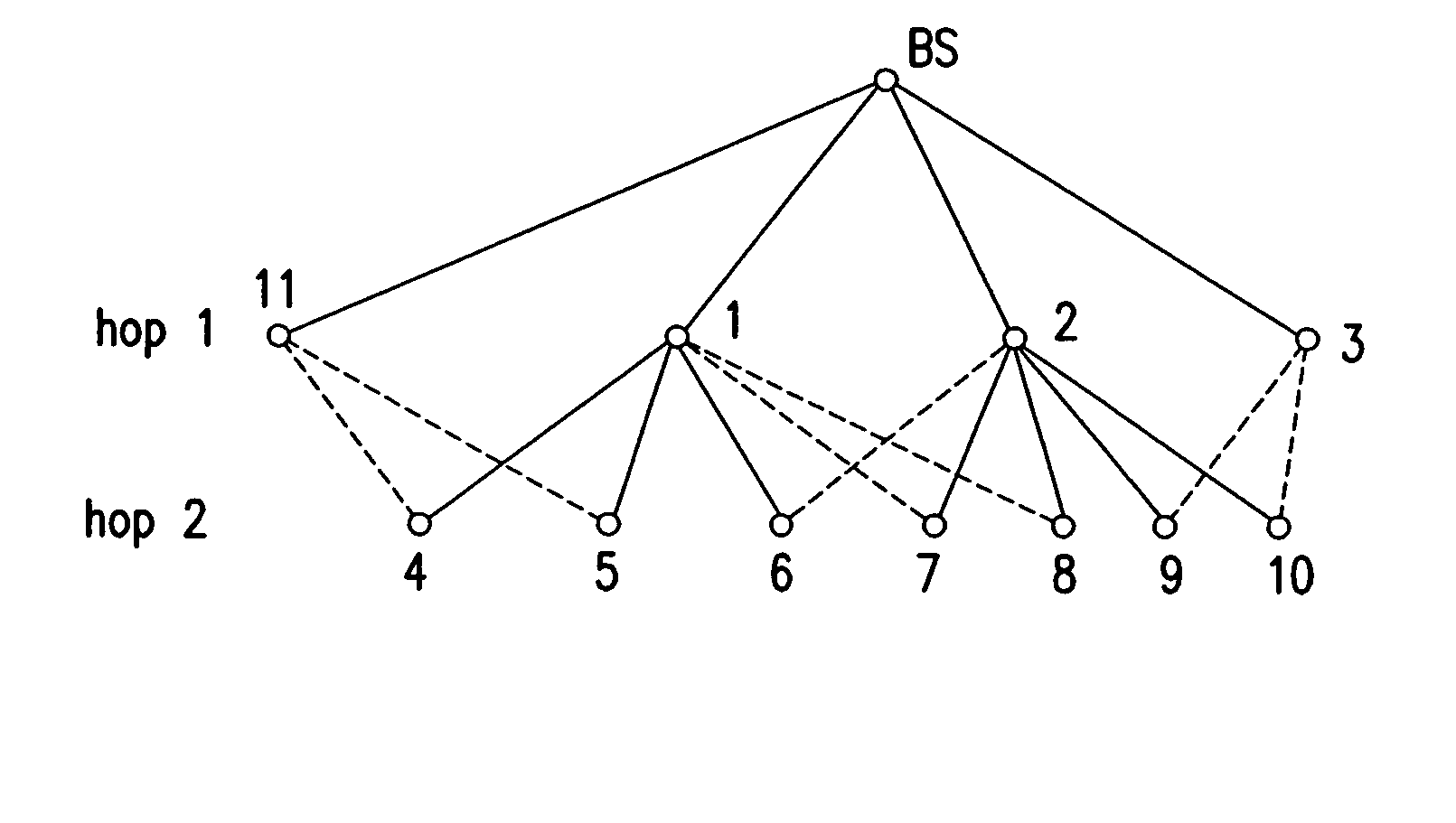
[0032]FIG. 2 shows an exemplary multihop network, which includes a base station BS and node elements 1 through 11 arranged in a hierarchical manner, where a solid line (also referred to as an edge) connecting two network node elements indicates a supervisory relationship between the two element nodes. In particular, the base station BS is configured to supervise node elements 1, 2, 3, and 11, node element 1 is configured to supervise node elements 4, 5 and 6, and node element 2 is configured to...


PUM


Abstract

A method and apparatus is provided to supervise a network, in which a first device supervises a network node element, and a second device partially supervises the network node element.

Description

CROSS REFERENCE TO RELATED APPLICATIONS[0001]This application is related to U.S. patent application Ser. No. 11 / 239,836 filed Sep. 30, 2005, and which issued on Nov. 3, 2009 as U.S. Pat. No. 7,613,146; U.S. patent application Ser. No. 11 / 239,837 filed Sep. 30, 2005, and which issued on May 19, 2009 as U.S. Pat. No. 7,536,194; U.S. patent application Ser. No. 11 / 240,401 filed Sep. 30, 2005; U.S. patent application Ser. No. 11 / 240,434 filed Sep. 30, 2005; U.S. patent application Ser. No. 11 / 240,436 filed Sep. 30, 2005, and which issued on Sep. 16, 2008 as U.S. Pat. No. 7,426,190; U.S. patent application Ser. No. 11 / 240,545 filed Sep. 30, 2005; U.S. patent application Ser. No. 11 / 241,296 filed Sep. 30, 2005; U.S. patent application Ser. No. 11 / 241,298 filed Sep. 30, 2005; and U.S. patent application Ser. No. 11 / 241,639 filed Sep. 30, 2005. The disclosure of each of the foregoing related applications is hereby incorporated by reference herein in its entirety.FIELD OF THE INVENTION[0002]...

Claims


Application Information

Patent Timeline
Patent Type & Authority Patents(United States)
IPC IPC(8): G06F15/173
CPCH04W24/00H04L43/10
Inventor MANJESHWAR, ARATIHERRMANN, FALK
Owner ROBERT BOSCH GMBH
Why Eureka
Try Eureka