
Method of printing a barcode using a line printhead, and a printing

a barcode and line printhead technology, applied in typewriters, visual presentations, instruments, etc., can solve the problems of time-consuming, lost bars, and inability to find such a continuous group of normal printing elements, and achieve the effect of reducing the number of barcode printing steps

Inactive Publication Date: 2014-03-04
SEIKO EPSON CORP
View PDF13 Cites 1 Cited by
  • Summary
  • Abstract
  • Description
  • Claims
  • Application Information

AI Technical Summary

Benefits of technology

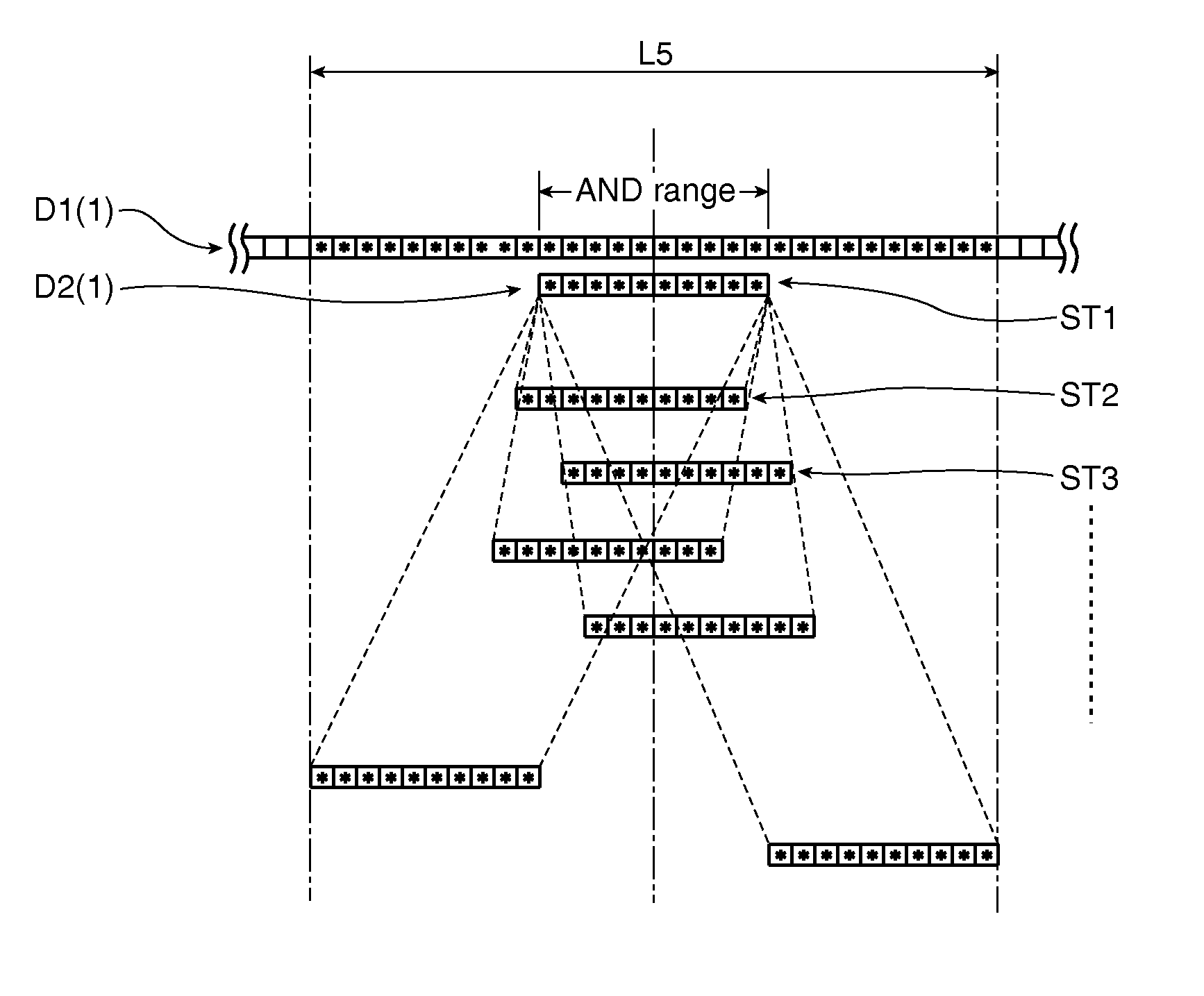
The patent text describes a method for printing barcodes on a line of products. The method first calculates a shift range for the barcode to be printed. The center of the barcode is aligned with the center of the shift range. Then, the print data is alternately shifted one printing element at a time left and right in the line direction to find a normal printing range where the barcode can be printed normally. This approach allows for faster and more efficient barcode printing than starting from the right or left end of the shift range. The overall efficiency of the barcode printing process is improved.

Problems solved by technology

As a result, if any of the printing elements of the line print head are damaged such that some print dots cannot be formed, bars may be lost or the bar width or space between the bars may vary, and the expected information may not be displayed.
If faulty printing elements are found at plural locations, finding such a continuous group of normal printing elements can be time-consuming.
Because this search operation restricts looking for printing elements that can print the barcode to a limited range, the likelihood of determining that printing the barcode is not possible and the barcode thus not being printed is high.
This method is therefore not practical.
This pattern-matching operation is time-consuming, however, and not efficient.
In addition, faulty heat elements in a thermal head include both heat elements that do not heat when energized, and heat elements that heat when not driven.
Methods of the related art that only treat elements that cannot form print dots as faulty printing elements can result in printing unnecessary print dots where there is supposed to be a space instead of a printed bar, and printing a defective barcode with wider than expected bars or no spaces where expected may be unavoidable.

Method used


Image

  • Method of printing a barcode using a line printhead, and a printing
  • Method of printing a barcode using a line printhead, and a printing
  • Method of printing a barcode using a line printhead, and a printing

Examples


Embodiment Construction

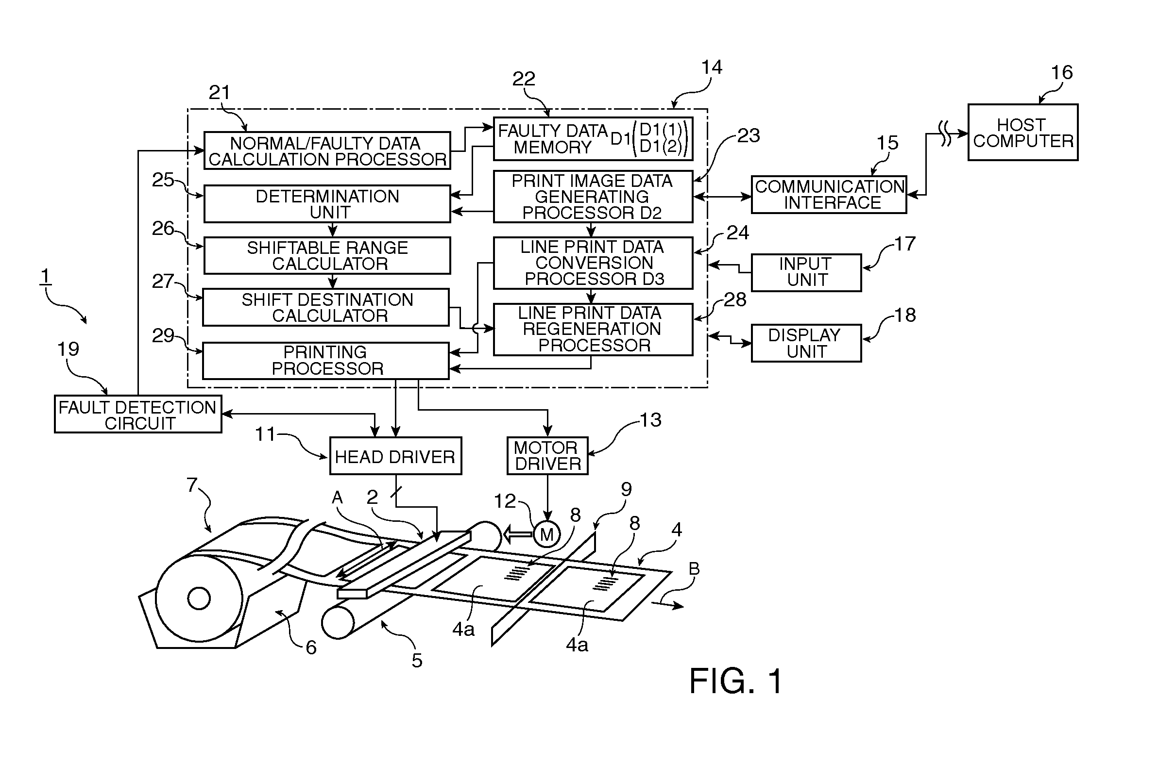
[0035]A preferred embodiment of a printing device having a line thermal head for printing barcodes according to the present invention is described below with reference to the accompanying figures.

General Configuration of Printing Device

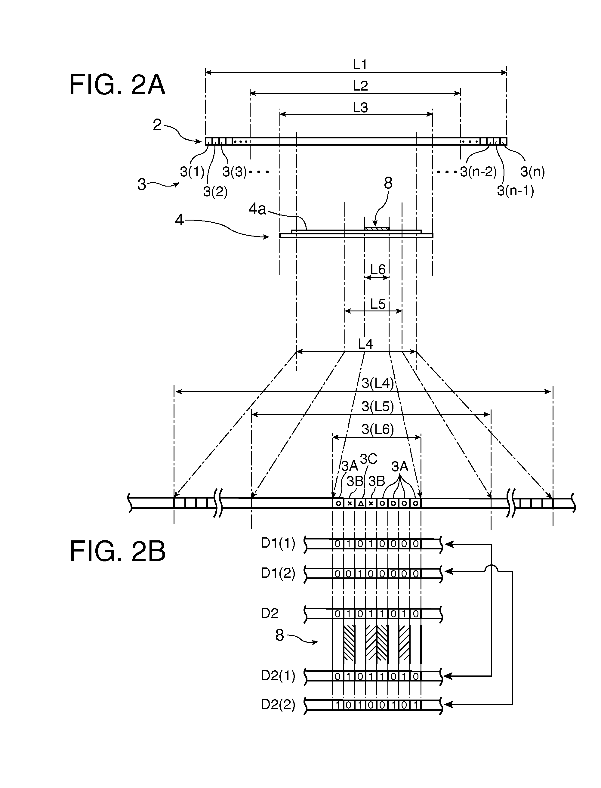
[0036]FIG. 1 schematically describes the configuration of a printing device according to this embodiment of the invention, and FIGS. 2A and 2B describe the barcode printing process.

[0037]As shown in these figures, the printing device 1 has a line thermal head 2 and a plurality of heat elements 3(1) to 3(n) (collectively referred to below as heat element 3) disposed on the line thermal head 2 in one row, for example, in the line direction A (widthwise to the printer). A platen roller 5 is pressed to the line thermal head 2 with the recording medium to be printed, such as label paper 4, therebetween. The label paper 4 is supplied from roll paper 7 stored in a roll paper compartment 6, for example. The label paper 4 is conveyed by the platen roller 5 in ...


PUM


Abstract

A barcode printing method can easily and quickly find the location of a group of consecutive printing elements that can print a barcode correctly when the line print head has faulty printing elements. The printing device determines the shift range for the barcode printing position, aligns the center of the barcode print data with the center of the shift range, from this position alternately shifts the print data one printing element at a time left and right in the line direction, and finds a group of consecutive printing elements that can print the barcode correctly. A normal printing range can thus be found in a short time with the smallest shift compared with searching from the end of the shift range, and the overall efficiency of a barcode printing operation that executes repeatedly can be improved.

Description

BACKGROUND[0001]1. Technical Field[0002]The present invention relates to a barcode printing method for printing barcodes using a line print head having printing elements arrayed in a line, and to a printing device for the same.[0003]2. Related Art[0004]One-dimensional barcodes that are printed using a line thermal head and have bars of specified widths formed in a specific pattern perpendicular to the transportation direction of the recording medium (referred to herein as “picket fence barcodes”) display information using the pattern of the bar widths and the spaces between the bars in the barcode. As a result, if any of the printing elements of the line print head are damaged such that some print dots cannot be formed, bars may be lost or the bar width or space between the bars may vary, and the expected information may not be displayed. To address this problem, a method of printing a barcode when some printing elements of the line print head are faulty and cannot print normally by...

Claims


Application Information

Patent Timeline
Patent Type & Authority Patents(United States)
IPC IPC(8): B41J2/01B41J29/38
CPCB41J2/2146G06K15/1868G06K1/121B41J3/01B41J2/2142G06K15/1889
Inventor ZAMA, MASANORIIWASA, YUYASHIMADA, SHUNICHIOMI, SHIGERU
Owner SEIKO EPSON CORP
Learn More