Vehicle interior panel, and airbag device

a technology for vehicle interior panels and airbags, which is applied in the direction of roofs, pedestrian/occupant safety arrangements, vehicular safety arrangements, etc., can solve the problems of increased manufacturing time and cost disadvantageous reduction of rigidity of vehicle interior panels, etc., to prevent the reduction of reduce the strength of the second welding rib, and reduce the rigidity of the entire panel

Inactive Publication Date: 2014-02-25
JOYSON SAFETY SYST JAPAN KK
View PDF30 Cites 4 Cited by
  • Summary
  • Abstract
  • Description
  • Claims
  • Application Information

AI Technical Summary

Benefits of technology

[0007]Accordingly, the present invention provides a vehicle interior panel and an airbag device capable of preventing a decrease in the weld strength and a decrease in the rigidity of the panel.
[0020]Yet still furthermore, by forming the fifth communication grooves on the joint surface of the flange portion located outside of the hinge portion so as not to be successively aligned in a direction perpendicular to the fifth welding ribs, the strength of the flange portion in a direction in which the fifth welding ribs are formed can be increased. In this way, a decrease in the rigidity of the entire panel can be prevented.

Problems solved by technology

However, if, like the vehicle interior panel with a surface skin described in Japanese Patent No. 4371780, a communication channel is provided in the welding rib in the longitudinal direction and the lateral direction, the rigidity of the vehicle interior panel is disadvantageously decreased.
As a result, in order to prevent part of the vehicle interior panel from scattering when an airbag is inflated and deployed, excessive vibration welding needs to be performed and, therefore, the manufacturing time and cost of the vehicle interior panel are increased.

Method used


Image

  • Vehicle interior panel, and airbag device
  • Vehicle interior panel, and airbag device
  • Vehicle interior panel, and airbag device

Examples


Embodiment Construction

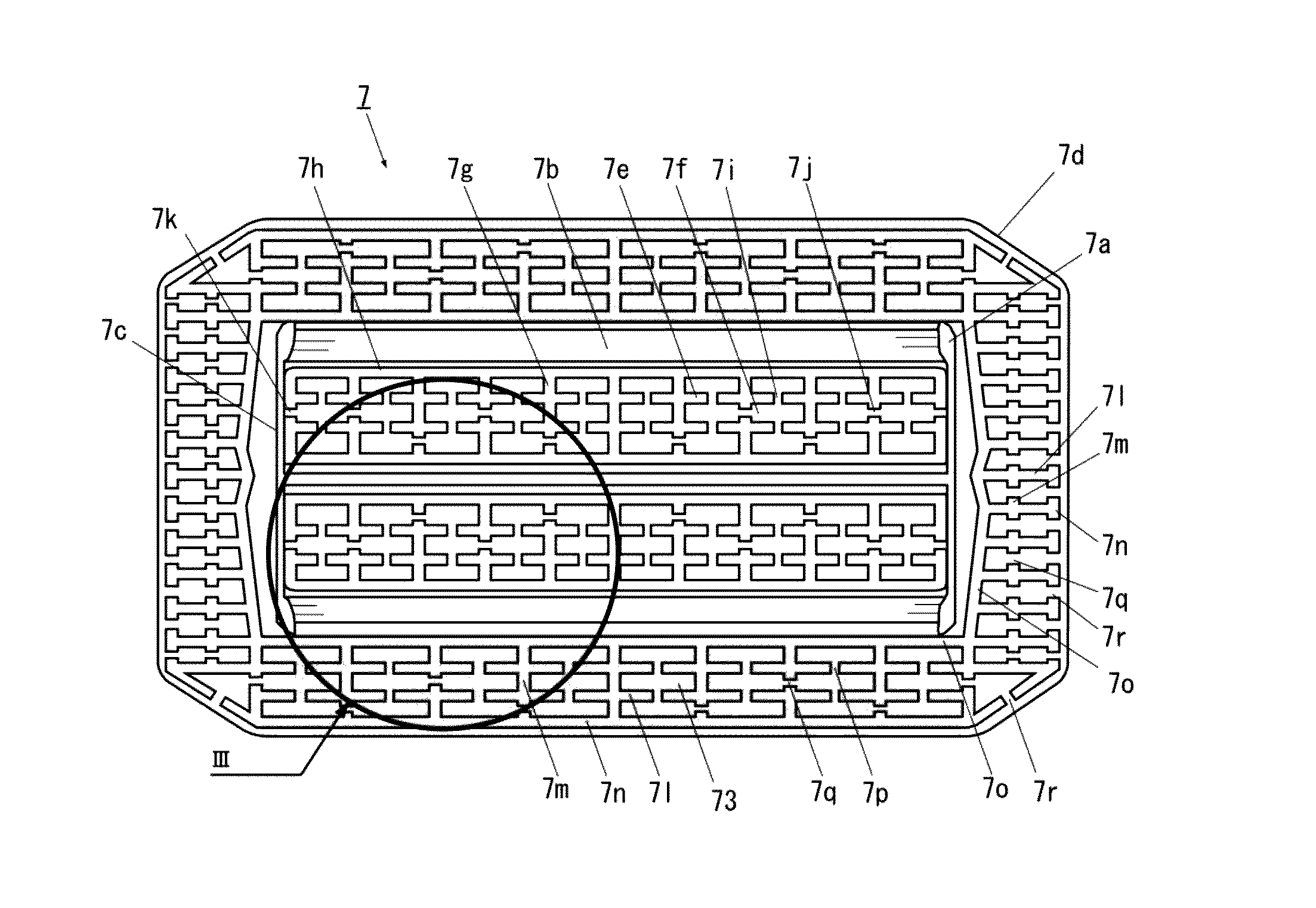
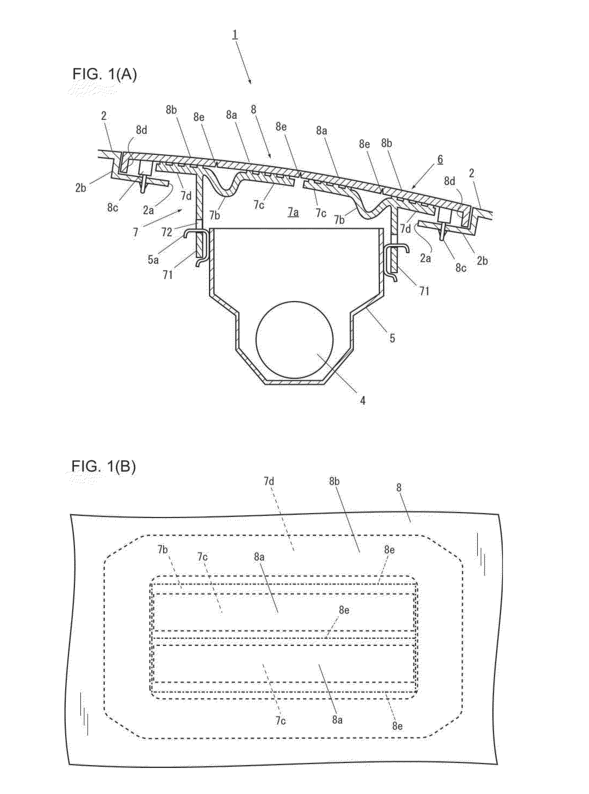
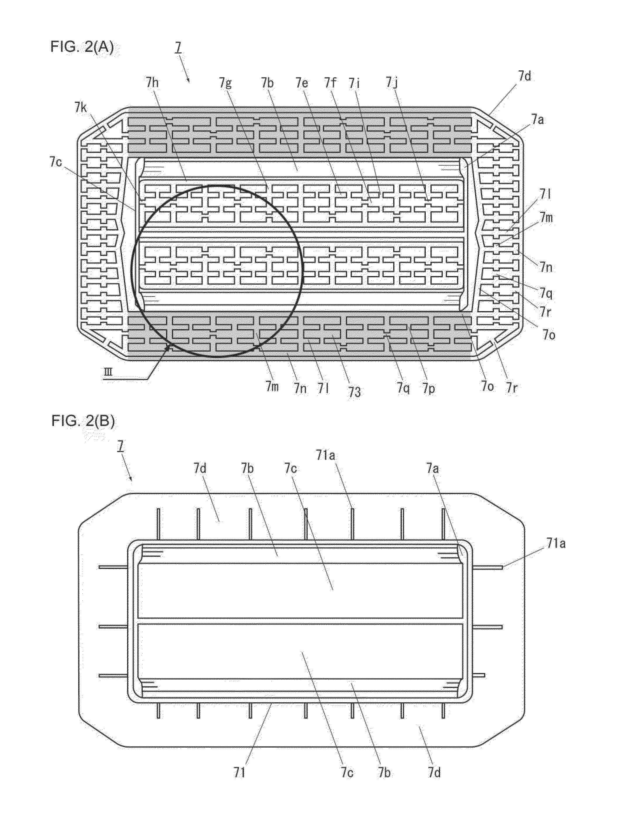
[0028]An airbag device and a vehicle interior panel according to an embodiment of the present invention are described below with reference to FIGS. 1-6. FIGS. 1(A) and 1(B) illustrate the airbag device according to an embodiment of the present invention, wherein FIG. 1(A) is a cross-sectional view of the airbag device, and FIG. 1(B) is a front view of the airbag device. In addition, FIGS. 2(A) and 2(B) illustrate an inner case illustrated in FIGS. 1(A) and 1(B), wherein FIG. 2(A) is a front view of the inner case, and FIG. 2(B) is a back view of the inner case. FIG. 3 is an enlarged view of a portion indicated by III in FIG. 2(A). Note that an airbag device 1 illustrated in FIGS. 1(A) and 1(B) represents an embodiment obtained when the present invention is applied to a passenger airbag device that is incorporated into an instrument panel 2 disposed in front of the passenger seat on the side adjacent to the vehicle body.

[0029]As illustrated in FIGS. 1(A) and 1(B), the airbag device 1...


PUM

PropertyMeasurementUnit
weld strengthaaaaaaaaaa
rigidityaaaaaaaaaa
strengthaaaaaaaaaa

Abstract

Provided are a vehicle interior panel and an airbag device wherein it is possible to prevent the weld strength and the rigidity of a panel from deteriorating. In a vehicle interior panel, a joint surface of a flap portion has first welding ribs, second welding ribs, and a third welding rib formed thereon. The first welding ribs include the first communication grooves each allowing adjacent grids and to communicate with each other. The second welding ribs include second communication grooves each allowing adjacent grids to communicate with each other. The third welding rib includes third communication grooves formed on sides substantially perpendicular to a hinge portion. The second communication grooves are formed so as not to be successively aligned in a direction perpendicular to the second welding ribs. The first to third communication grooves form an exhaust channel allowing the air in the grids to be discharged outside during vibration welding.

Description

CROSS-REFERENCE TO RELATED APPLICATIONS[0001]This application is a U.S. national phase application filed under 35 U.S.C. §371 of International Application PCT / JP2011 / 054452, filed on Feb. 28, 2011, designating the United States, which claims priority from JP 2010-048397, filed on Mar. 4, 2010, which are hereby incorporated herein by reference in their entirety.FIELD OF THE INVENTION[0002]The present invention relates to a vehicle interior panel and an airbag device mounted in a vehicle, such as an automobile, and, in particular, to a vehicle interior panel and an airbag device joined by vibration welding.BACKGROUND OF THE INVENTION[0003]In general, a vehicle interior panel is formed by joining an inner case to an outer panel using vibration welding. The inner case has an opening for deploying an airbag and a flap portion formed together with a hinge portion in the opening. The outer panel covers the surface of the inner case and includes a door portion to be joined to the flap porti...

Claims


Application Information

Patent Timeline
Patent Type & Authority Patents(United States)
IPC IPC(8): B62D25/14B60R21/215B60R21/205
CPCB60R21/2165B60R21/215B29C66/30223B29C65/06B29C66/301B60R2021/21537B29C66/342B29C66/234B29C66/54B29L2031/3038B29C66/545B29C66/9512B29C66/542B29C66/9516B29C66/543B29C66/1122B29C66/131
Inventor KANNO, YUKI
Owner JOYSON SAFETY SYST JAPAN KK
Why Eureka
Try Eureka