Method, system, and tool for affixing compression stabilized prosthetic socket interface

a compression stabilized prosthetic and socket technology, applied in the field of prosthetic limbs, can solve the problems of excessive thickness and no prior design has specifically allowed for tissue displacemen

Active Publication Date: 2014-02-25
ALLEY RANDALL D MR
View PDF41 Cites 26 Cited by
  • Summary
  • Abstract
  • Description
  • Claims
  • Application Information

AI Technical Summary

Benefits of technology

[0017]In a preferred embodiment of the invention, a mold (negative model) is made by making a cast of a remaining limb on which a prosthesis will be used. From the mold / cast, a positive model is made of the remaining limb. There are deep channels formed in the positive model, which are a cause of excessive thickness in these areas when conventional lamination procedures are used. Where the areas between the channels are to be left open, however, the model may be brought almost flush with the edges of the compressed areas. This alteration permits a much stronger lamination. Another technique to strengthen the resulting struts is to corrugate the compression channel area to create a resistance to flex upon lamination.
[0018]When taking a cast of the area above the knee, prosthetists are often assisted by using jigs especially to establish the shape of the brim area for transfemoral sockets. In the new socket technology of this invention, one may also use a jig to assist in achieving an optimal cast of the area above the knee.

Problems solved by technology

There are deep channels formed in the positive model, which are a cause of excessive thickness in these areas when conventional lamination procedures are used.
From the inventor's knowledge, no prior designs have specifically allowed for the displacement of tissue as a requirement for achieving stability even if local compressed areas exist.

Method used


Image

  • Method, system, and tool for affixing compression stabilized prosthetic socket interface
  • Method, system, and tool for affixing compression stabilized prosthetic socket interface
  • Method, system, and tool for affixing compression stabilized prosthetic socket interface

Examples


Embodiment Construction

)

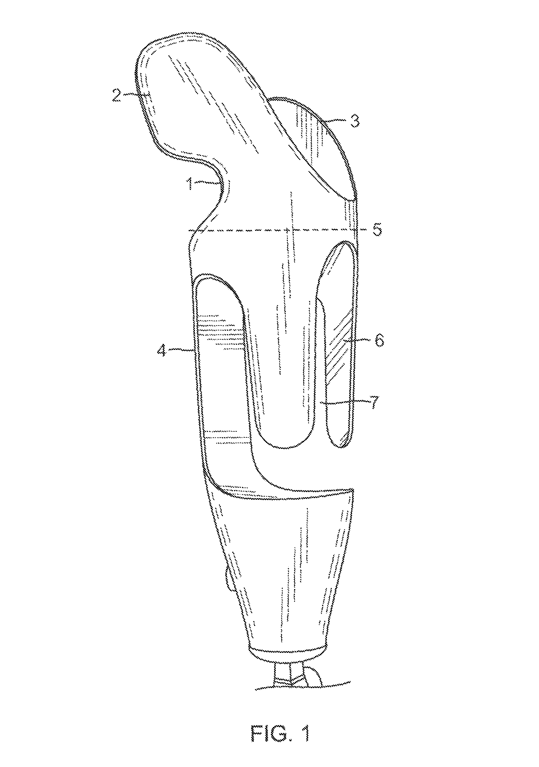
[0083]As shown in FIG. 1, a the transhumeral open-cage interface embodiment, there is an upper portion 1, which has both an anterior stabilizer 2 and a posterior stabilizer 3 and which extends in a proximal (in this case toward a patient's shoulder) and medial (toward a patient's midline) direction from a lower portion 4 to stabilize the interface on a patient's body. Although stabilizers 2 and 3 are not required, they are recommended to impart or enhance rotational stability. The lower portion 4 (below line 5) has an open-cage structure. Dashed horizontal line 5 demarcates the upper and lower portions. The lower portion 4 of this open-cage embodiment has multiple, e.g. three or four struts 6, which look like fingers that extend along the long axis of the residual limb and are designed to partially encompass the residual limb, allowing soft tissue to flow through windows 7.

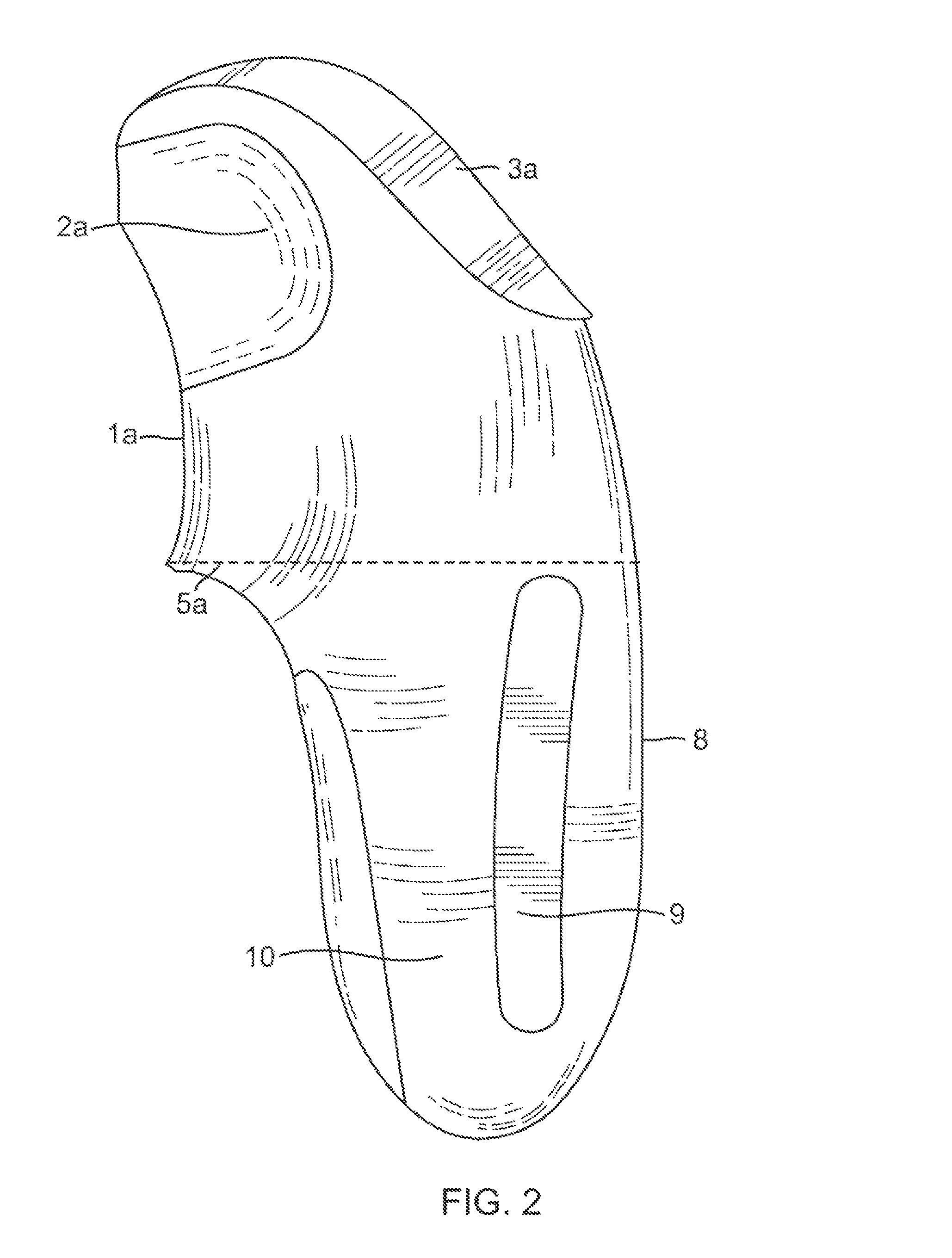
[0084]As shown in FIG. 2, a transhumeral solid-body interface embodiment, there is an upper portion 1a, which ...


PUM


Abstract

A method, system, and tool for fitting a compression stabilized prosthetic socket for a patient having an amputated limb and a remaining portion that includes a first socket portion for contacting a patient's remaining portion of a limb, and a second socket portion for attachment of a prosthetic device. The first socket portion has compression portions having a radius for compressing portions of the patient's remaining portion of a limb, and relief portions receiving any portions of the patient's remaining limb which bulge upon the compression applied by the compression portions. The relief portions may be formed as openings or as enlarged radius portions. The fitting method, system, and tool can include use of a mechanism to compress bar surfaces against the limb in areas selected to receive compression portions in order to prepare an image for creating the first socket portion.

Description

CROSS REFERENCE TO RELATED APPLICATION(S)[0001]This application is a continuation-in-part of, and claims the benefit of priority from U.S. patent application Ser. No. 12 / 945,876, filed Nov. 14, 2010, now U.S. Pat. No. 8,323,353, which in turn is a continuation-in-part of, and claims the benefit of priority from U.S. patent application Ser. No. 12 / 792,728, filed Jun. 2, 2010, now abandoned, which in turn is a continuation-in-part of, and claims the benefit of priority from U.S. patent application Ser. No. 12 / 380,861, filed Mar. 4, 2009, now abandoned, which in turn claims benefit of U.S. Provisional Patent Application No. 61 / 068,263, filed Mar. 4, 2008, all four of such applications are incorporated by reference herein.FIELD OF THE INVENTION[0002]The present invention relates to the prosthetic limbs worn by upper or lower limb amputees and in particular, to the portion of a limb prosthesis that is in direct contact with the user's skin.DEFINITIONS OF TERMS[0003]Socket—is that part of...

Claims


Application Information

Patent Timeline
Patent Type & Authority Patents(United States)
IPC IPC(8): A61G15/00
CPCA61F2/76A61F2/80B33Y80/00G06F30/00
Inventor ALLEY, RANDALL D.WILLIAMS, III, T. WALLEY
Owner ALLEY RANDALL D MR
Why Eureka
Try Eureka