
D/A conversion circuit, A/D conversion circuit and electronic apparatus

a conversion circuit and conversion circuit technology, applied in the direction of digital-analog convertors, transmission systems, instruments, etc., can solve the problems of circuit large-scale development and reduced conversion accuracy of d/a conversion circuits, and achieve the effect of enhancing apparent capacitance ratio accuracy and enhancing conversion accuracy

Active Publication Date: 2014-02-18
SEIKO EPSON CORP
View PDF8 Cites 4 Cited by
  • Summary
  • Abstract
  • Description
  • Claims
  • Application Information

AI Technical Summary

Benefits of technology

[0007]An advantage of some aspects of the invention is to provide a D / A conversion circuit, an A / D conversion circuit including the same and an electronic apparatus which are capable of enhancing apparent capacitance ratio accuracy to enhance conversion accuracy.

Problems solved by technology

However, in a case where the D / A conversion circuit is realized as a semiconductor IC, device variation occurs due to fluctuation in the manufacturing process or the like, and the conversion accuracy of the D / A conversion circuit is reduced due to the device variation.
On the other hand, for example, if the layout area of the capacitor is enlarged in order to enhance the capacitance ratio accuracy, there arises a problem that the circuit becomes large-scaled.

Method used


Image

  • D/A conversion circuit, A/D conversion circuit and electronic apparatus
  • D/A conversion circuit, A/D conversion circuit and electronic apparatus
  • D/A conversion circuit, A/D conversion circuit and electronic apparatus

Examples


Embodiment Construction

[0055]Hereinafter, preferred embodiments of the invention will be described in detail. It should be noted that the present embodiments described below do not unreasonably limit the content of the invention as set forth in the claims, and all of the configurations set forth in the present embodiments are not necessarily essential as means for solving the problems of the invention.

1. Configuration

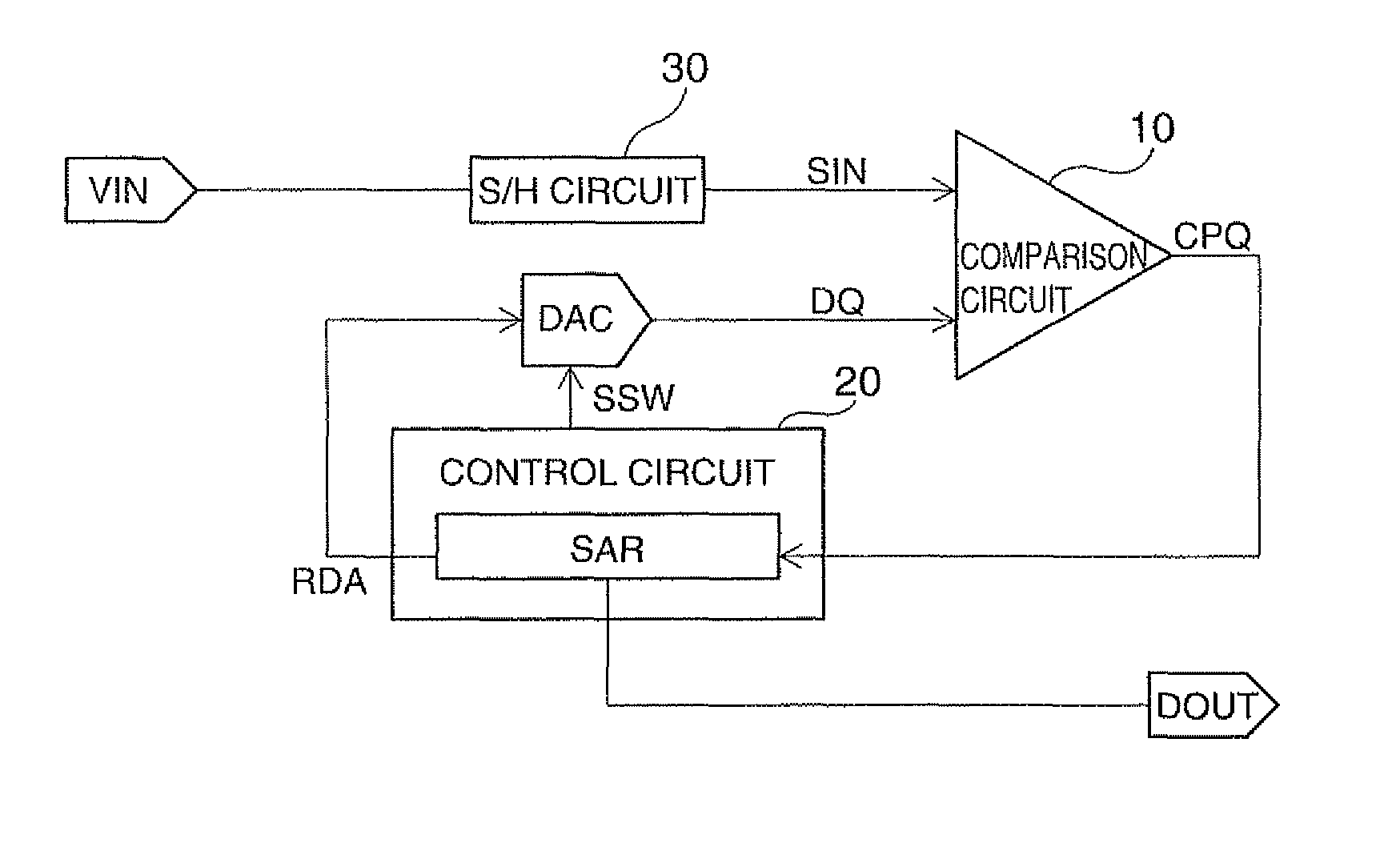
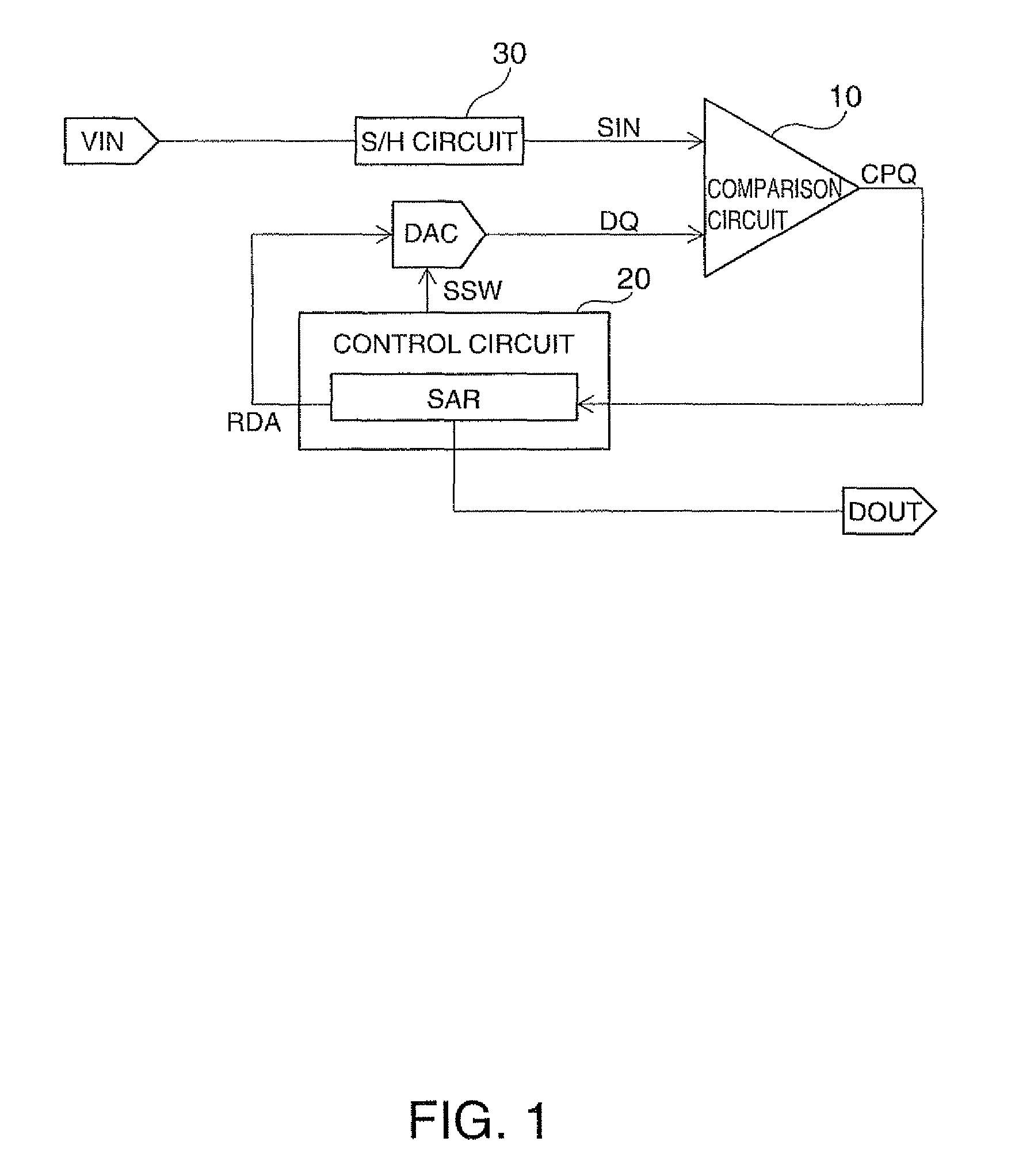
[0056]FIG. 1 shows a configuration example of an A / D conversion circuit in which a D / A conversion circuit is used according to an embodiment of the invention. The A / D conversion circuit includes a D / A conversion circuit DAC, a comparison circuit 10, and a control circuit 20. Further, the A / D conversion circuit may include an S / H (sample and hold) circuit 30.

[0057]Hereinafter, an example in which the D / A conversion circuit of the present embodiment is applied to a successive approximation type A / D conversion circuit is described, but the present embodiment is not limited thereto. For example, ...


PUM


Abstract

A D / A conversion circuit includes a first D / A converting section which is connected with an output node, a first serial capacitor which is disposed between the output node and a first node, a second D / A converting section which is connected with the first node, and a control circuit. The first D / A converting section includes a first capacitor array section and a first switch array section. The second D / A converting section includes a second capacitor array section and a second switch array section. The control circuit performs a switch control for dynamically changing allocation of the capacitors to the respective bits of input digital data for the first switch array section of the first D / A converting section.

Description

BACKGROUND[0001]1. Technical Field[0002]The present invention relates to a D / A conversion circuit, an A / D conversion circuit, an electronic apparatus, and the like.[0003]2. Related Art[0004]In the related art, as an A / D conversion circuit for converting an analog signal into digital data, a successive approximation type A / D conversion circuit has been proposed. The successive approximation type A / D conversion circuit is provided with a comparison circuit, a successive approximation register, and a D / A conversion circuit, and performs A / D conversion by sampling (performing a sample and hold operation for) an input signal and a successive approximation operation to output digital data. As such a successive approximation type A / D conversion circuit in the related art, a technique disclosed in JP-A-8-321779 is known.[0005]In such a successive approximation type A / D conversion circuit, most of the conversion accuracy depends on the accuracy of the D / A conversion circuit, the accuracy of ...

Claims


Application Information

Patent Timeline
Patent Type & Authority Patents(United States)
IPC IPC(8): H03M1/66
CPCH03M1/687H03M1/066H03M1/804H03M1/806H03M1/468
Inventor HANEDA, HIDEOYONEZAWA, TAKEMI
Owner SEIKO EPSON CORP
Learn More