
Low resistance stacked annular contact

a technology of annular contact and low resistance, which is applied in the direction of diodes, semiconductor devices, semiconductor/solid-state device details, etc., can solve the problems of forming a low resistance stacked contact, and achieve the effect of equal length and width

Active Publication Date: 2014-02-18
MIDWEST COMMUNITY DEV FUND IV +1
View PDF6 Cites 2 Cited by
  • Summary
  • Abstract
  • Description
  • Claims
  • Application Information

AI Technical Summary

Benefits of technology

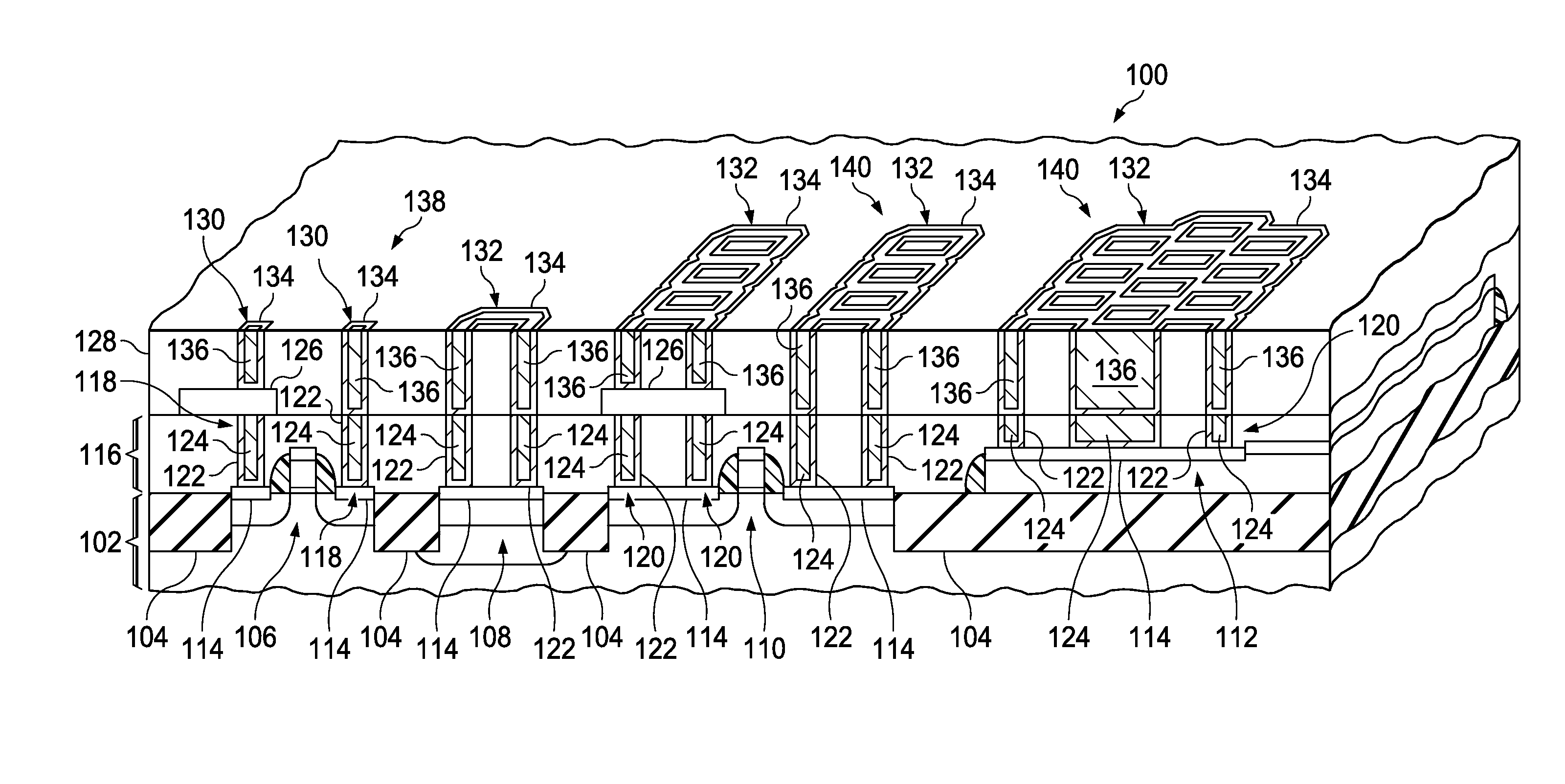
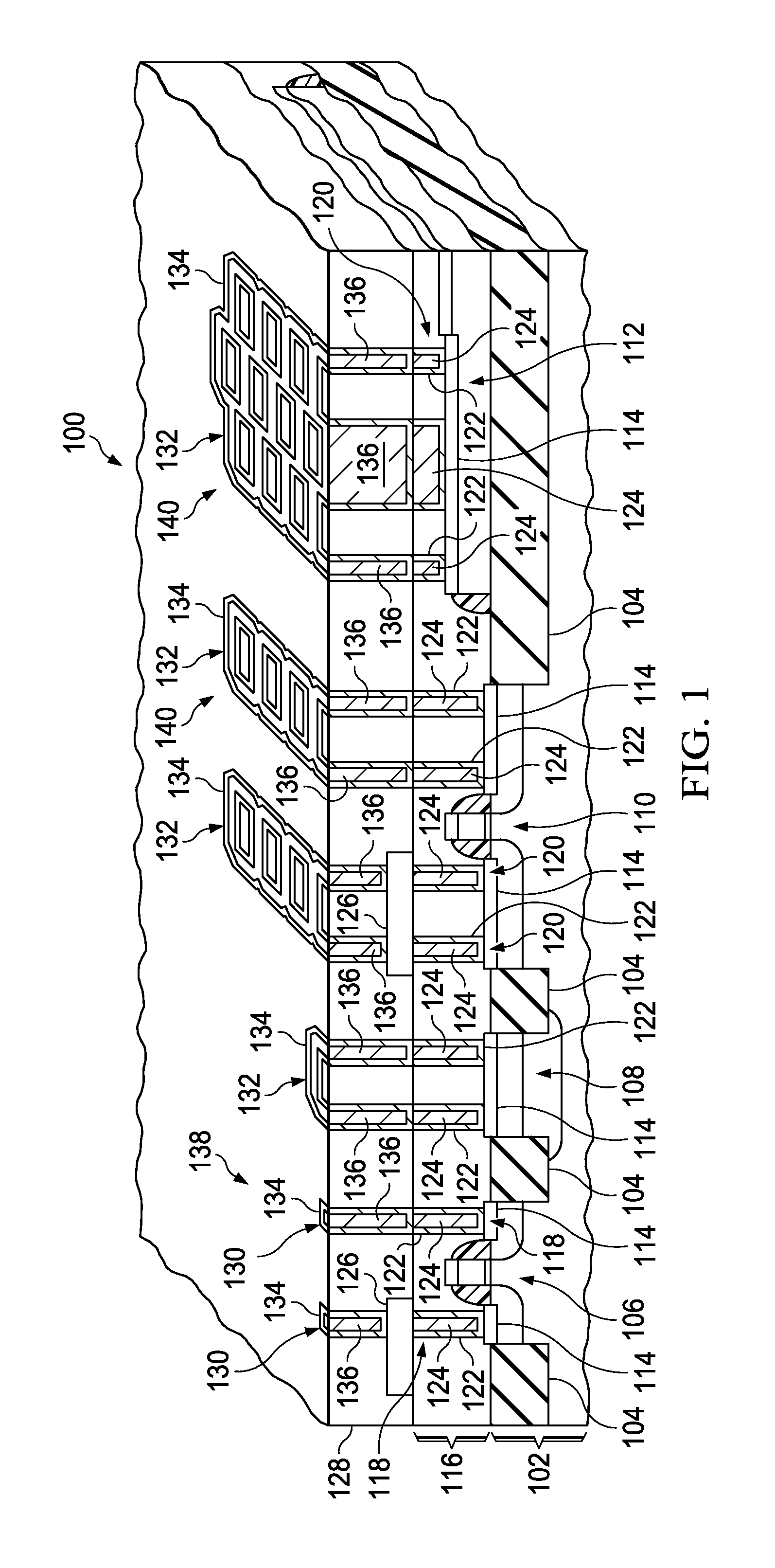
[0006]Upper components such as ferroelectric capacitors or other memory components, resistors, capacitors, and / or thin film transistors are formed over the PMD layer. An ILD layer is formed over the upper components and the PMD layer. Upper contact holes are etched through the ILD layer, including conventional contact holes and annular contact holes, aligned with corresponding conventional lower contacts and annular lower contacts. A width of the annular holes in the annular contact holes is 0.75 to 2.5 times a width of the conventional contact holes. A pillar of ILD layer material surrounded by the annular holes in the annular contact holes has substantially equal length and width, being 1 to 4 times a width of the conventional contact holes. A layer of metal upper liner is formed is formed in the upper contact holes and over a top surface of the ILD layer, and a layer of upper contact metal is formed on the upper liner in the upper contact holes and over the top surface of the ILD layer. The upper contact metal and upper liner are subsequently removed from over the top surface of the ILD layer, forming upper contacts making electrical connections to the corresponding lower contacts. The upper contacts include conventional upper contacts in the conventional contact holes and annular upper contacts in the annular contact holes. A width of the annular metal in the annular upper contacts is 0.75 to 2.5 times a width of the conventional upper contacts. The pillar of ILD layer material surrounded by the annular metal is 1 to 4 times the width of the conventional upper contacts. Top surfaces of conventional upper contacts and annular upper contacts are substantially coplanar with the top surface of the ILD layer. A combination of an instance of the lower annular contacts electrically connected to a corresponding instance of the upper annular contacts forms a stacked annular contact. Similarly, a combination of an instance of the conventional lower contacts electrically connected to a corresponding instance of the conventional upper contacts forms a conventional stacked contact. A level of metal interconnects is formed over the ILD layer having metal interconnect lines which make electrical connections to the stacked annular contacts. The stacked annular contacts may advantageously provide lower resistance connections between the first interconnect level and the lower components in the substrate and on the field oxide than conventional stacked contacts in a same area as the annular stacked contact.

Problems solved by technology

Such a process limits the width of the lower contact and the upper contact, so that forming a low resistance stacked contact may be problematic.

Method used


Image

  • Low resistance stacked annular contact
  • Low resistance stacked annular contact
  • Low resistance stacked annular contact

Examples


Embodiment Construction

[0011]The present invention is described with reference to the attached figures. The figures are not drawn to scale and they are provided merely to illustrate the invention. Several aspects of the invention are described below with reference to example applications for illustration. It should be understood that numerous specific details, relationships, and methods are set forth to provide an understanding of the invention. One skilled in the relevant art, however, will readily recognize that the invention can be practiced without one or more of the specific details or with other methods. In other instances, well-known structures or operations are not shown in detail to avoid obscuring the invention. The present invention is not limited by the illustrated ordering of acts or events, as some acts may occur in different orders and / or concurrently with other acts or events. Furthermore, not all illustrated acts or events are required to implement a methodology in accordance with the pre...


PUM


Abstract

An integrated circuit contains lower components in the substrate, a PMD layer, upper components over the PMD layer, lower contacts in the PMD layer connecting some upper components to some lower components, an ILD layer over the upper components, metal interconnect lines over the ILD layer, and upper contacts connecting some upper components to some metal interconnect lines, and also includes annular stacked contacts of lower annular contacts aligned with upper annular contacts. The lower contacts and upper contacts each have a metal liner and a contact metal on the liner. The lower annular contacts have at least one ring of liner metal and contact metal surrounding a pillar of PMD material, and the upper contacts have at least one ring of liner metal and contact metal surrounding a pillar of ILD material. The annular stacked contacts connect the metal interconnects to the lower components.

Description

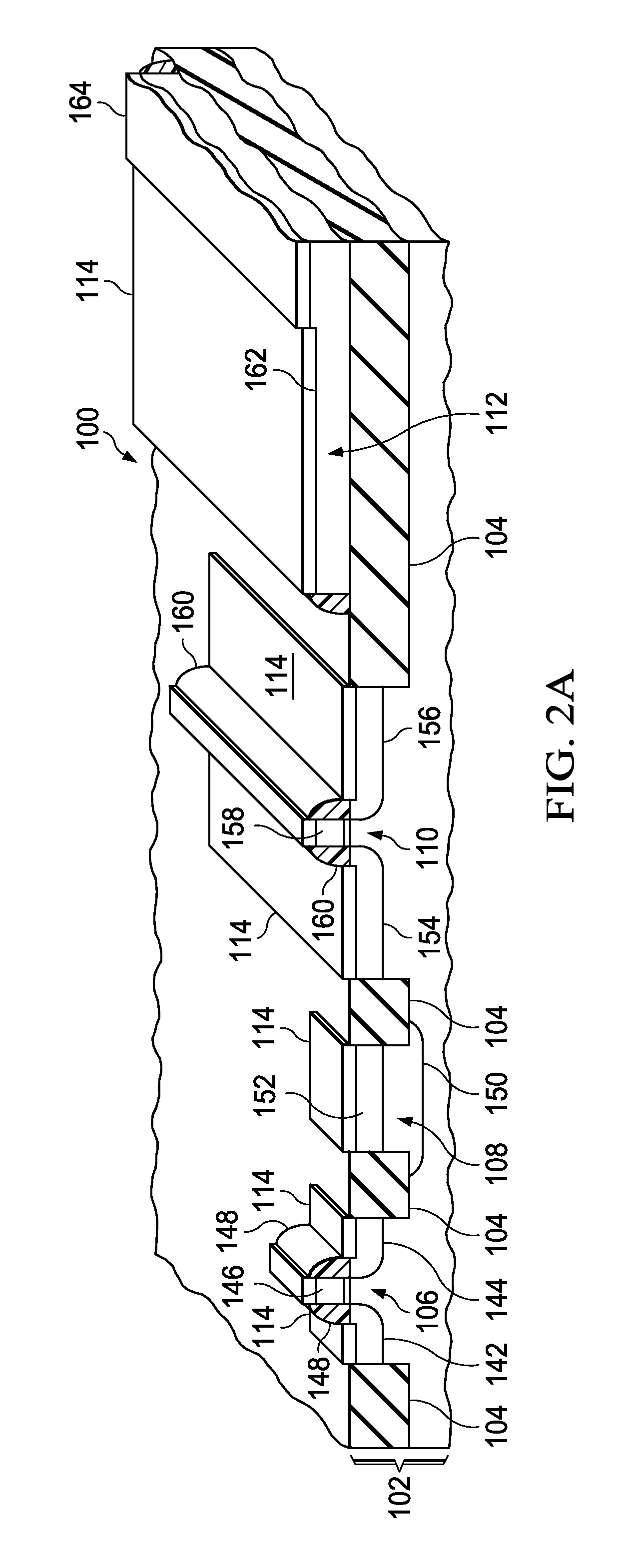
CROSS-REFERENCE TO RELATED APPLICATIONS[0001]This application claims the benefit of U.S. Provisional Application 61 / 468,634, filed Mar. 29, 2011, the entirety of which is herein incorporated by reference.FIELD OF THE INVENTION[0002]This invention relates to the field of integrated circuits. More particularly, this invention relates to contacts in integrated circuits.BACKGROUND OF THE INVENTION[0003]An integrated circuit may include a pre-metal dielectric (PMD) layer and an inter-level dielectric (ILD) layer between a semiconductor substrate and a first metal interconnect level. Upper components, such as ferroelectric capacitors, may be formed between the PMD layer and the ILD layer. Contacts between lower components in and on the substrate and the first metal interconnect level may be stacked contacts including a lower contact lower contact formed in the PMD layer and an upper contact formed in the ILD layer. The lower contact and the upper contact may be formed by depositing contac...

Claims


Application Information

Patent Timeline
Patent Type & Authority Patents(United States)
IPC IPC(8): H01L23/48H01L21/8242H01L21/108H01L21/00H01L21/02
CPCH01L23/485H01L23/5256H01L21/76843H01L21/76838H01L23/5226H01L23/5283H01L21/76816H01L23/528H01L27/0629H01L2924/0002H01L2924/00
Inventor SUMMERFELT, SCOTT ROBERTRAHMAN, HASIBURCAMPBELL, JOHN PAUL
Owner MIDWEST COMMUNITY DEV FUND IV
Learn More