Single and double door storage rack

a storage rack and single door technology, applied in the direction of dismountable cabinets, manufacturing tools, curtain suspension devices, etc., can solve the problems of limiting the type and amount of equipment that can be stored on the panel, limiting the amount of air circulation within the cabinet, and limiting the visual inspection and access of the tools on the other panel. , to achieve the effect of expanding the storage capacity of the rack system

Active Publication Date: 2014-02-18
GEAR GRID
View PDF41 Cites 15 Cited by
  • Summary
  • Abstract
  • Description
  • Claims
  • Application Information

AI Technical Summary

Benefits of technology

[0007]The door and back panels consist of a wire grid of generally equidistantly spaced and parallel pairs of horizontal bars and vertical bars, although other configurations are possible. The grid panels provide a surface for conveniently and selectively mounting holders for tools, equipment, clothing or other articles. Tool holders can be mounted on the front of the back panel and on either or both sides of the door panels. The panels permit a visual confirmation of what tools, equipment, clothing or other articles are stored on the rack and that the holders and supported articles are properly mounted on the rack. Further, air is permitted to flow through the rack to help dry any articles stored on the rack.
[0008]In a second embodiment, two door panels are pivotally mounted to the mounting assembly in opposing relation (on opposite sides of the mounting assembly). A first door panel will have its axis of rotation located opposite and forward of the axis of rotation of the second door panel. This further expands the storage capability of the rack system, providing five panel sides for mounting equipment.

Problems solved by technology

Frequently, the tool positions on the panel are fixed and cannot be changed, limiting the type and amount of equipment that can be stored on the panel.
Further, if one panel is fully extended outward to give the firemen access to the tools mounted on the panel, it may block visual inspection of and access to the tools on the other panels.
Further, the doors limit the amount of air circulation within the cabinet.
If some of the equipment is wet when mounted on the tool holders within the cabinet, the tools may not adequately dry out, leading to rust or decay.

Method used


Image

  • Single and double door storage rack
  • Single and double door storage rack
  • Single and double door storage rack

Examples


Embodiment Construction

[0027]Even though numerous characteristics and advantages of the present invention have been set forth in the following description, together with details of the structure and function of the invention, the disclosure is illustrative only, and changes may be made in detail, especially in matters of shape, size, and arrangement of parts within the principles of the invention to the full extent indicated by the broad general meaning of the terms in which the appended claims are expressed.

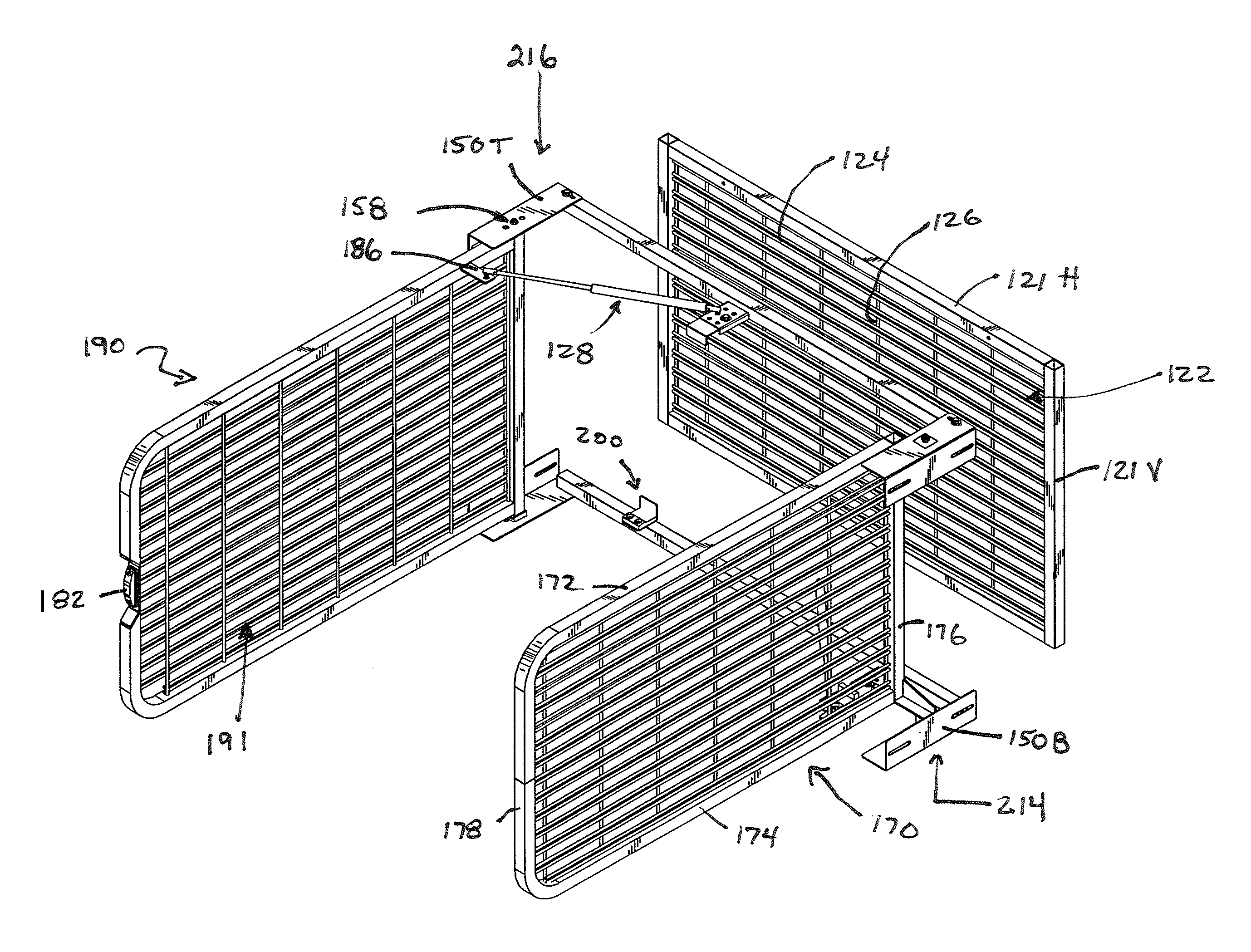
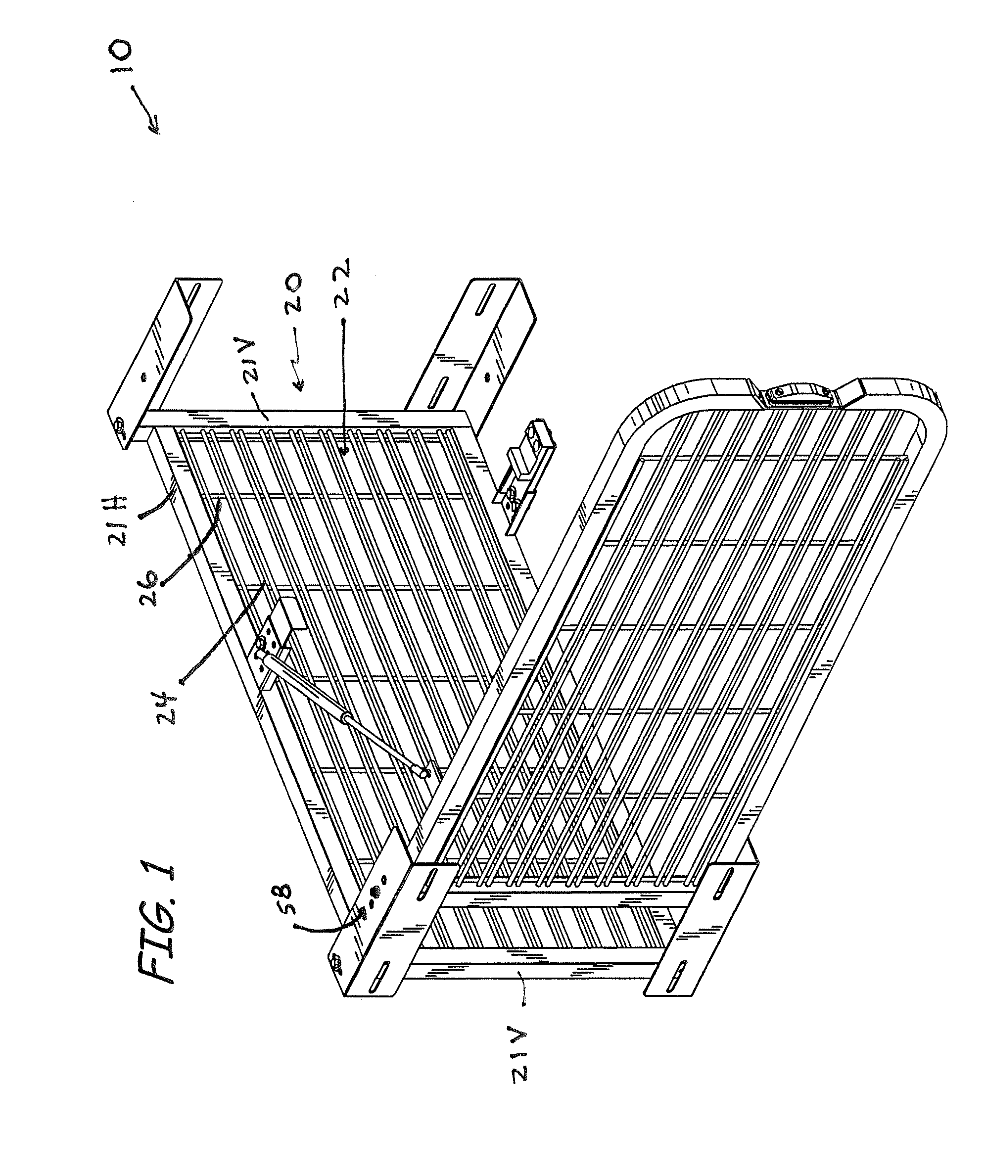
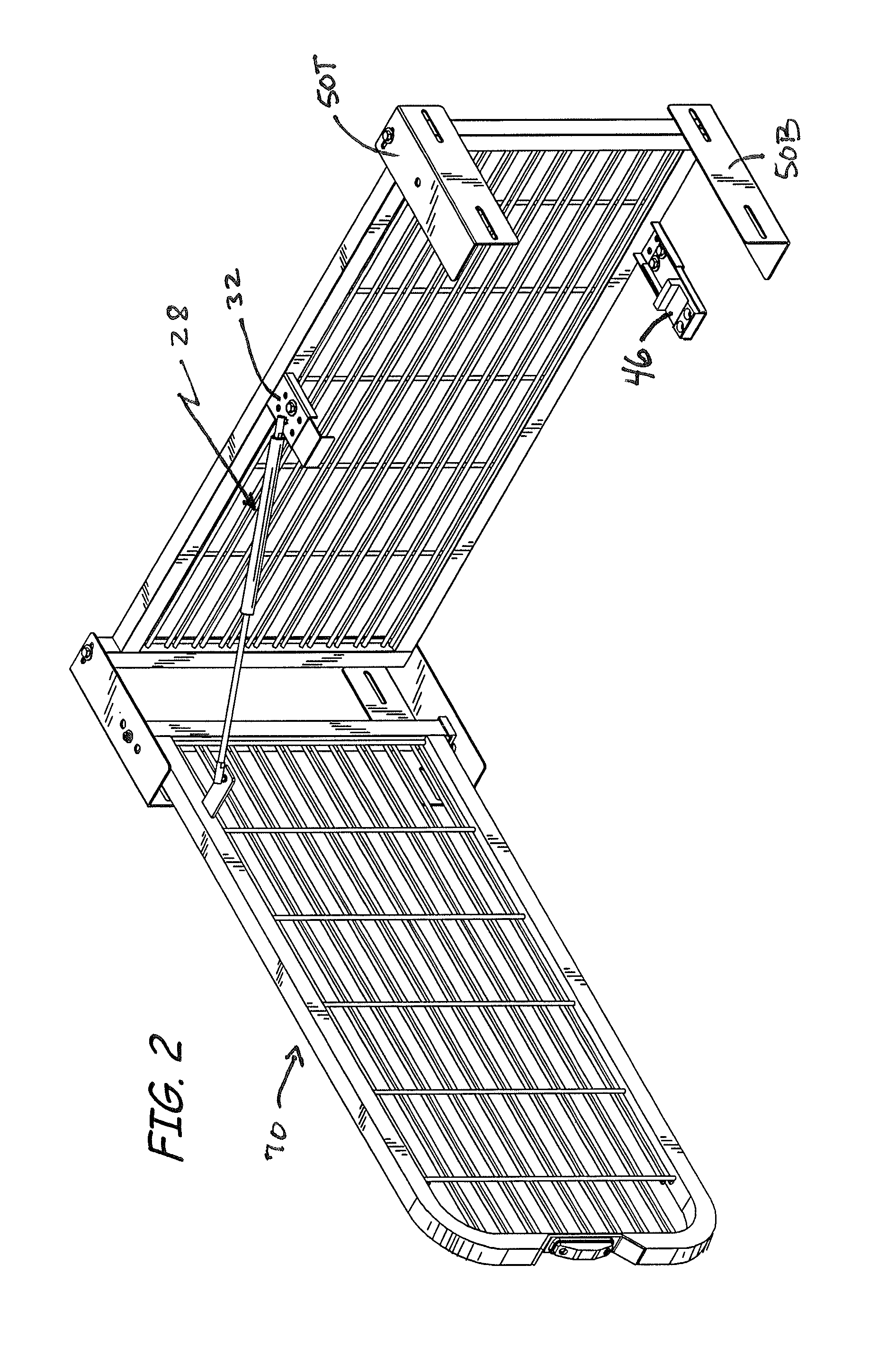
[0028]A single door panel embodiment of the storage rack of the present invention is shown at 10 in FIG. 1. The storage rack 10 is designed to be mounted within a recess in the side of a motor vehicle or a wall in a building. The storage rack 10 includes a generally rectangular back panel 20, a mounting assembly 50 and a generally rectangular door panel 70 pivotally mounted between two vertically aligned mounting members. Door panel 70 rotates between a closed position substantially parallel to the ba...


PUM


Abstract

The invention is a compact storage rack for holding and storing tools and other articles within a recess in a wall of a building or vehicle. The storage rack includes a back panel, mounting members for securing the rack in the recess and at least one door panel pivotally mounted to the mounting members. Each panel consists of a wire grid composed of pairs of generally parallel and equidistantly spaced horizontal bars secured together by generally parallel and equidistant vertical bars. The grid design allows visual inspection of the tools inside the storage rack to confirm what equipment is present and that it is properly mounted. The grid design also allows air to permeate the storage rack to air dry the tools stored therein. The swing door arrangement provides easy access to the equipment.

Description

FIELD OF THE INVENTION[0001]The invention relates to compact tool storage racks. The present invention is useful for, amongst other things, holding and storing equipment within a recess located in the side or back of rescue trucks, fire trucks or other vehicles as well as recesses in walls of buildings.BACKGROUND OF THE INVENTION[0002]Common equipment storage racks for rescue or fire trucks include vertical aluminum panels slidably mounted within a recess located in the side of a truck for movement between a retracted or stored position fully within the truck recess and an extended position substantially extended outward from the truck. When the panels are fully extended from the truck recess, the tools mounted on the panel can be accessed.[0003]Frequently, the tool positions on the panel are fixed and cannot be changed, limiting the type and amount of equipment that can be stored on the panel. Further, typically two or more panels are slidably mounted side by side in the recess to ...

Claims


Application Information

Patent Timeline
Patent Type & Authority Patents(United States)
IPC IPC(8): A47H1/00
CPCB60R5/003B25H3/04
Inventor BOYER, MICHAEL, C.
Owner GEAR GRID
Why Eureka
Try Eureka