Patient lift and transfer device

a technology for lifting and transferring patients, which is applied in the field of patient lifts, can solve the problems of unsteady swinging movement of the sling, making the patient uncomfortable, undignification, etc., and achieves the effect of steady and smooth transportation

Active Publication Date: 2014-02-18
LIN TSUNG YI
View PDF10 Cites 7 Cited by
  • Summary
  • Abstract
  • Description
  • Claims
  • Application Information

AI Technical Summary

Benefits of technology

[0010]An object of the present invention is to provide a patient lift and transfer device which has a resting module for a patient to sit or lie thereon and which can hoist the patient steadily and safely without swinging of the resting module so that the patient may feel relatively comfortable.
[0011]According to this invention, the patient lift and transfer device includes a base provided with casters for moving on a ground surface, a mast and a guiding post which extend in an upright direction from the base and which are spaced apart from each other in a longitudinal direction, a carriage including a carriage body which is sleeved on and linearly displaceable relative to the mast, a beam which extends cantileveredly and forwardly from the carriage body, and a guided member which extends from the carriage body and which is in slidable engagement with the guiding post, a mechanical linear drive assembly disposed to drive movement of the carriage body along the mast, and a resting module including a major wall which extends in the longitudinal direction to terminate at proximate and distal sides, and which has an insert slot that is configured to permit the beam to be detachably engaged therein to thereby suspend the major wall from the ground surface. A patient may sit or lie on the resting module and may be lifted with movement of the carriage by operation of the mechanical linear drive assembly so as to be steadily and smoothly transported.

Problems solved by technology

1. Since the hydraulic cylinder is used as the actuator, the lifting arm 15 is moved and stopped abruptly, thereby rendering swinging movement of the sling 17 unsteadily and making the patient uncomfortable.
2. Since the fabric-made sling 17 is wrapped around the patient, the patient may feel very uncomfortable on his / her back and legs, and may feel undignified when suspended in the sling 17.
3. A skilled and experienced operator is required to rapidly and safely wrap the sling 17 around the patient.

Method used


Image

  • Patient lift and transfer device
  • Patient lift and transfer device
  • Patient lift and transfer device

Examples


second embodiment

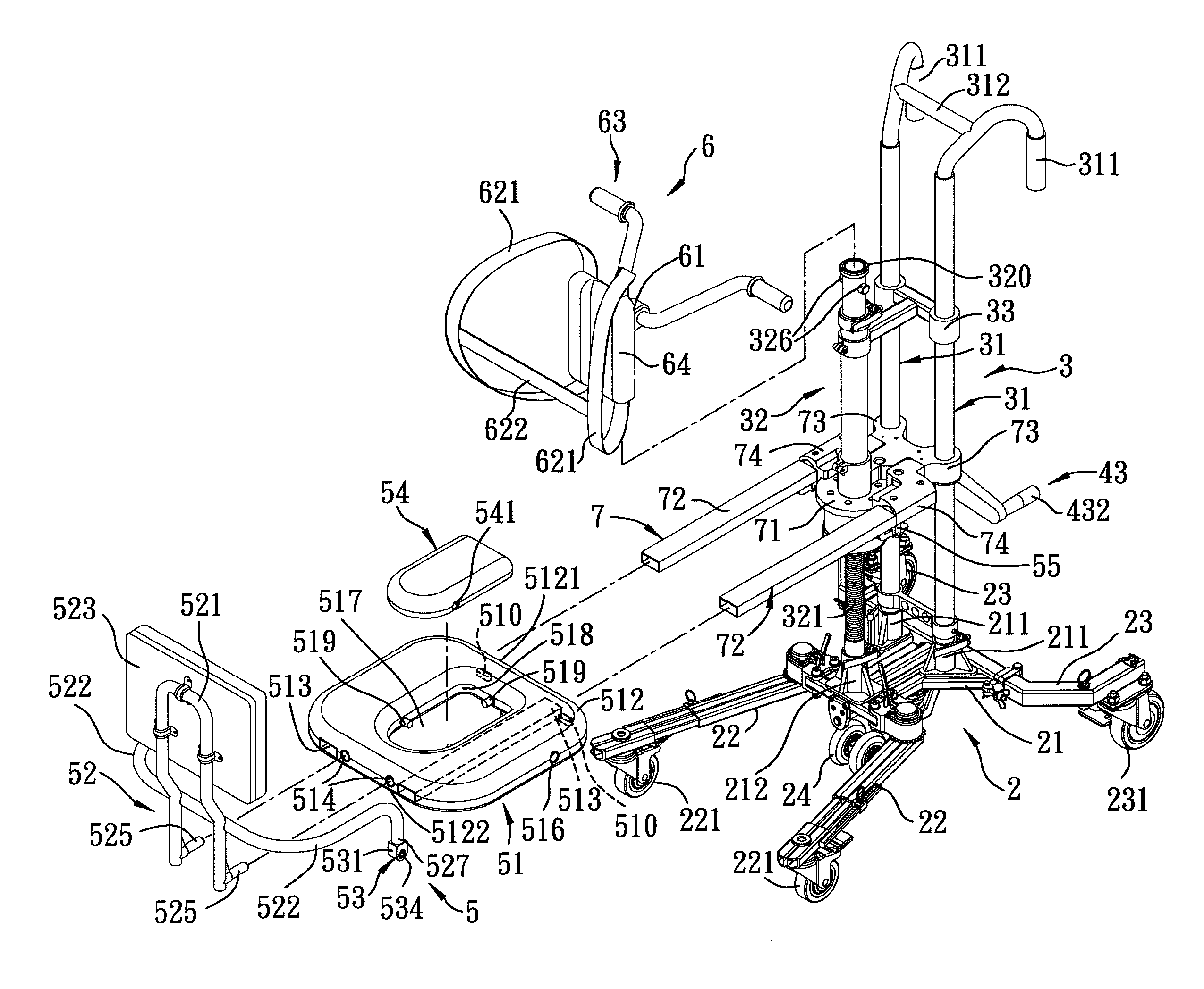
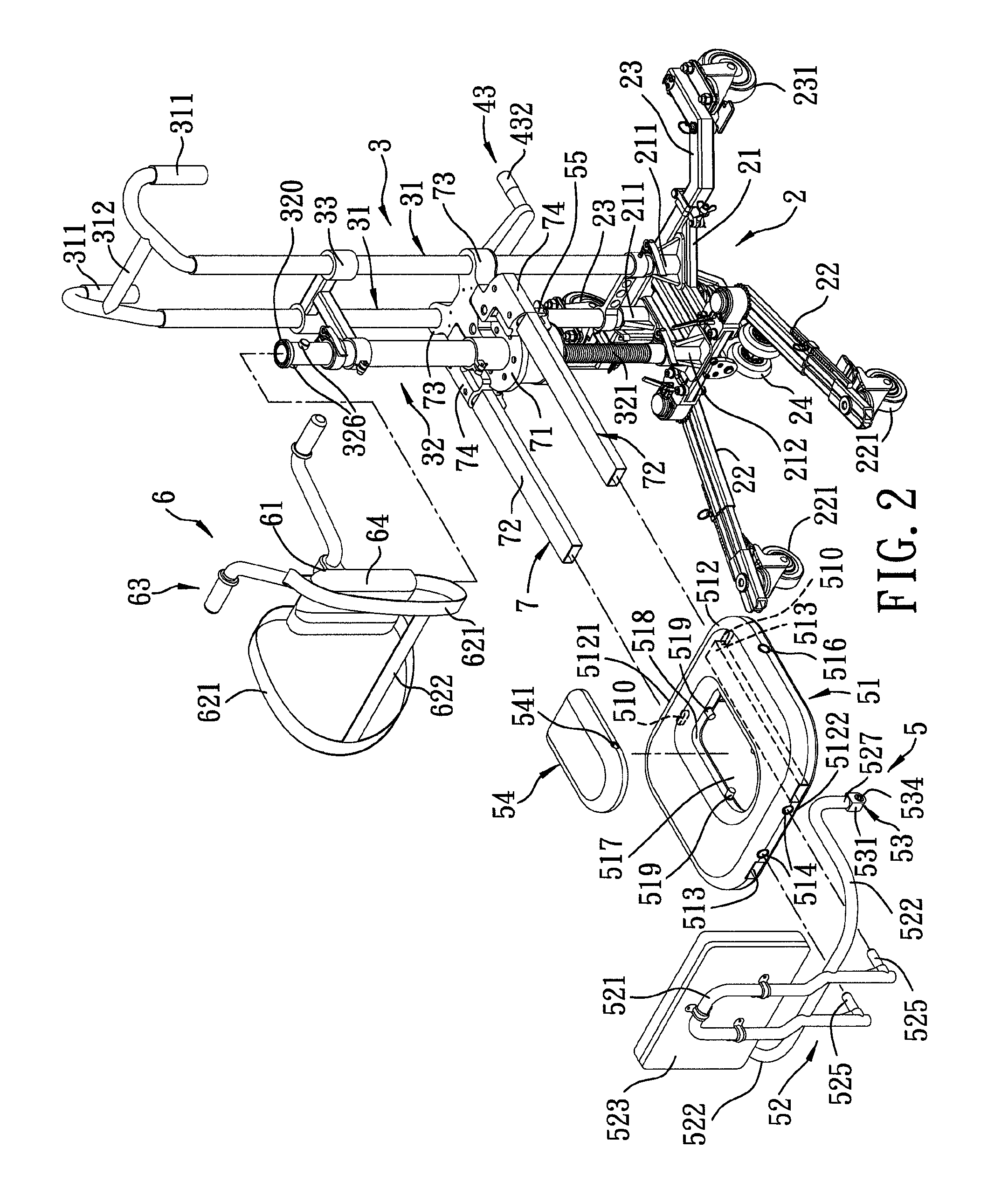
[0041]Referring to FIGS. 7 and 8, the second preferred embodiment of a patient lift and transfer device according to this invention is similar to the previous embodiment in construction. In the second embodiment, the chest guard module 6 includes a base mount 61 disposed to rest on the upper coupling end 320 of the mast 32, a chest guard body 64 disposed forwardly of the base mount 61, and a tabletop 66 mounted on top ends 313 of the guiding posts 31. Thus, a patient seated on the resting module 51 can place his / her arms on the tabletop 66 during the transfer process.

third embodiment

[0042]Referring to FIGS. 9 and 10, the third preferred embodiment of a patient lift and transfer device according to this invention is similar to the previous embodiments in construction. In the third embodiment, the resting module 51 is in the form of a stretcher 51 having a rectangular major wall 512 for a patient to lie thereon. Instead of the chest guard module 6, the device comprises two holding straps 67 which are connected to the distal side 5122 of the major wall 512 and the upper coupling end 320 of the mast 32 for holding the stretcher 51.

[0043]As illustrated, since the resting module 51 is retainingly connected to the carriage 7 and is lifted by means of the mechanical linear drive assembly 4 along the mast 32, a patient can be securely supported on the resting module 51 and can be smoothly and steadily lifted and transported. Moreover, since the resting module 51 is rigid, the patient seated or lying thereon can feel safer and more comfortable.


PUM


Abstract

A patient lift and transfer device includes a base with casters for moving on a ground surface, a mast extending upwardly from the base, a carriage guided to slide along the mast by a mechanical linear drive assembly and having a forwardly extending beam, and a resting module for a patient to sit or lie thereon. The resting module is detachably connected to the beam to be suspended from the ground surface, and is raised or lowered with the carriage so as to lift and transfer the patient in a safe and comfortable manner.

Description

CROSS-REFERENCE TO RELATED APPLICATION[0001]This application claims priority of Chinese Patent Application No. 200910252765.3, filed on Dec. 16, 2009, the disclosure of which is herein incorporated by reference.BACKGROUND OF THE INVENTION[0002]1. Field of the Invention[0003]This invention relates to a lift and transfer device, more particularly to a patient lift and transfer device which is used to lift and transfer a physically disabled patient to a wheelchair, a gurney, a commode, or a car seat.[0004]2. Description of the Related Art[0005]Referring to FIG. 1, a conventional patient lift is shown to include a rectangular base 11, a plurality of castors 12 for facilitating movement of the patient lift over a ground surface, a mast 13 extending rearwardly and upwardly from the base 11, two handles 14 securedly mounted on the mast 13, a lifting arm 15 which is pivotally mounted on and which extends forwardly from the mast 13 to terminate at a lifting end 151, an actuator 16, such as a...

Claims


Application Information

Patent Timeline
Patent Type & Authority Patents(United States)
IPC IPC(8): A61G7/10
CPCA61G7/1019A61G7/1088A61G7/1067A61G7/1059A61G7/1057A61G7/1046
Inventor LIN, TSUNG-YI
Owner LIN TSUNG YI
Why Eureka
Try Eureka