
Ink jet recording apparatus

a recording apparatus and jet technology, applied in the direction of printing, other printing apparatus, etc., can solve the problems of deterioration of tubes and more susceptible to failure, and achieve the effect of effectively preventing tubes from moving

Active Publication Date: 2014-02-11
SEIKO EPSON CORP
View PDF10 Cites 7 Cited by
  • Summary
  • Abstract
  • Description
  • Claims
  • Application Information

AI Technical Summary

Benefits of technology

The invention relates to an ink jet recording apparatus that can effectively prevent a tube from moving in response to a pulling force and restore it to its original state when the pulling force is released. This feature prevents deterioration and failures in the tube and ensures stable operation of the ink jet recording apparatus. The invention also provides a highly-stable ink jet recording apparatus by using the tube support member to support the ink tube that connects the main recording apparatus body to the tank unit that is removable from the main recording apparatus body. The invention also simplifies the configuration of the ink jet recording apparatus by supporting multiple bridging tube portions at the same time.

Problems solved by technology

In other words, with the stated configuration, there is a problem in that the residual tension continues to act even after the pulling force has been released, and thus not only does the cross-sectional surface area of the tube change, but the tube deteriorates more easily, is more susceptible to failures, and so on.

Method used


Image

  • Ink jet recording apparatus
  • Ink jet recording apparatus
  • Ink jet recording apparatus

Examples


Embodiment Construction

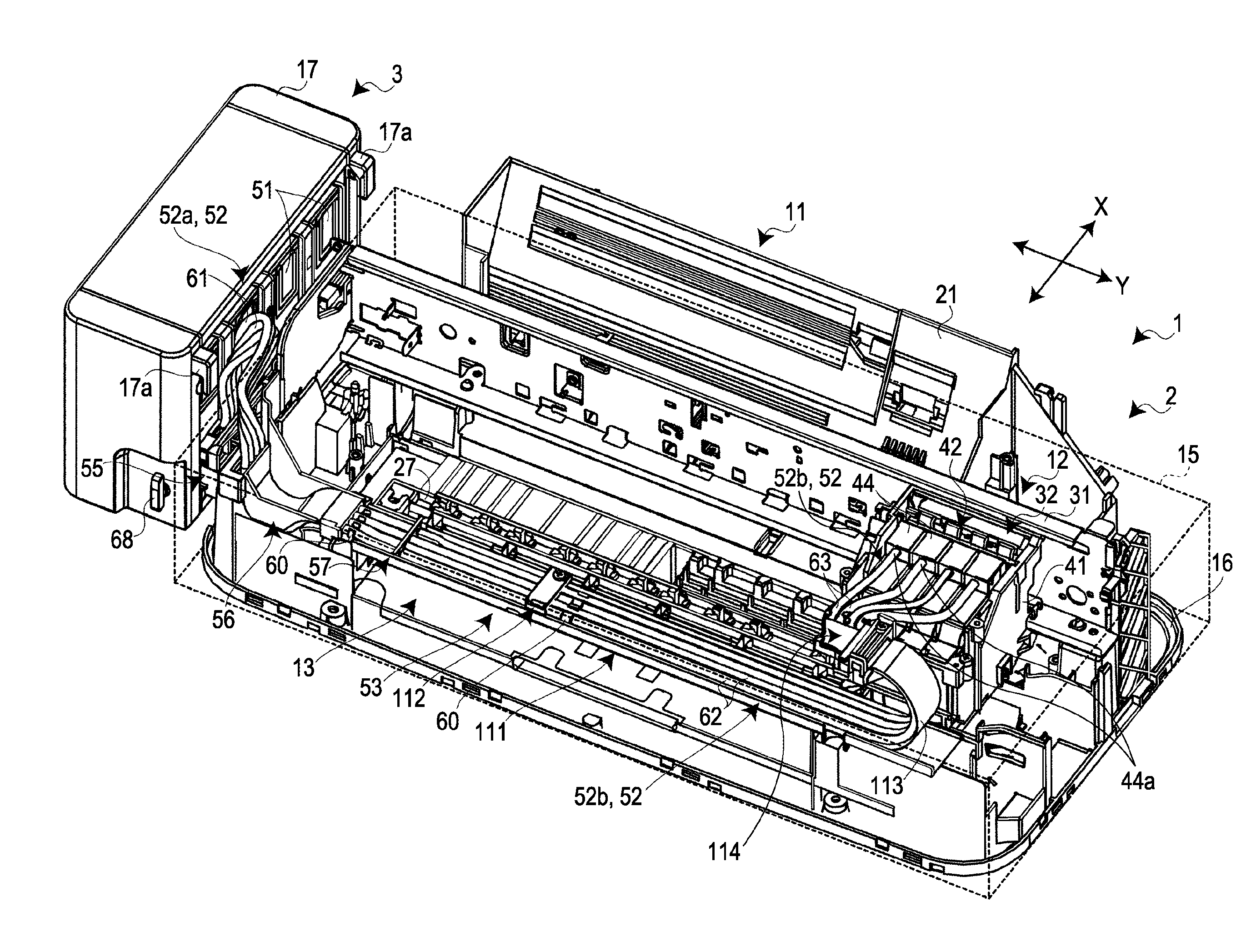
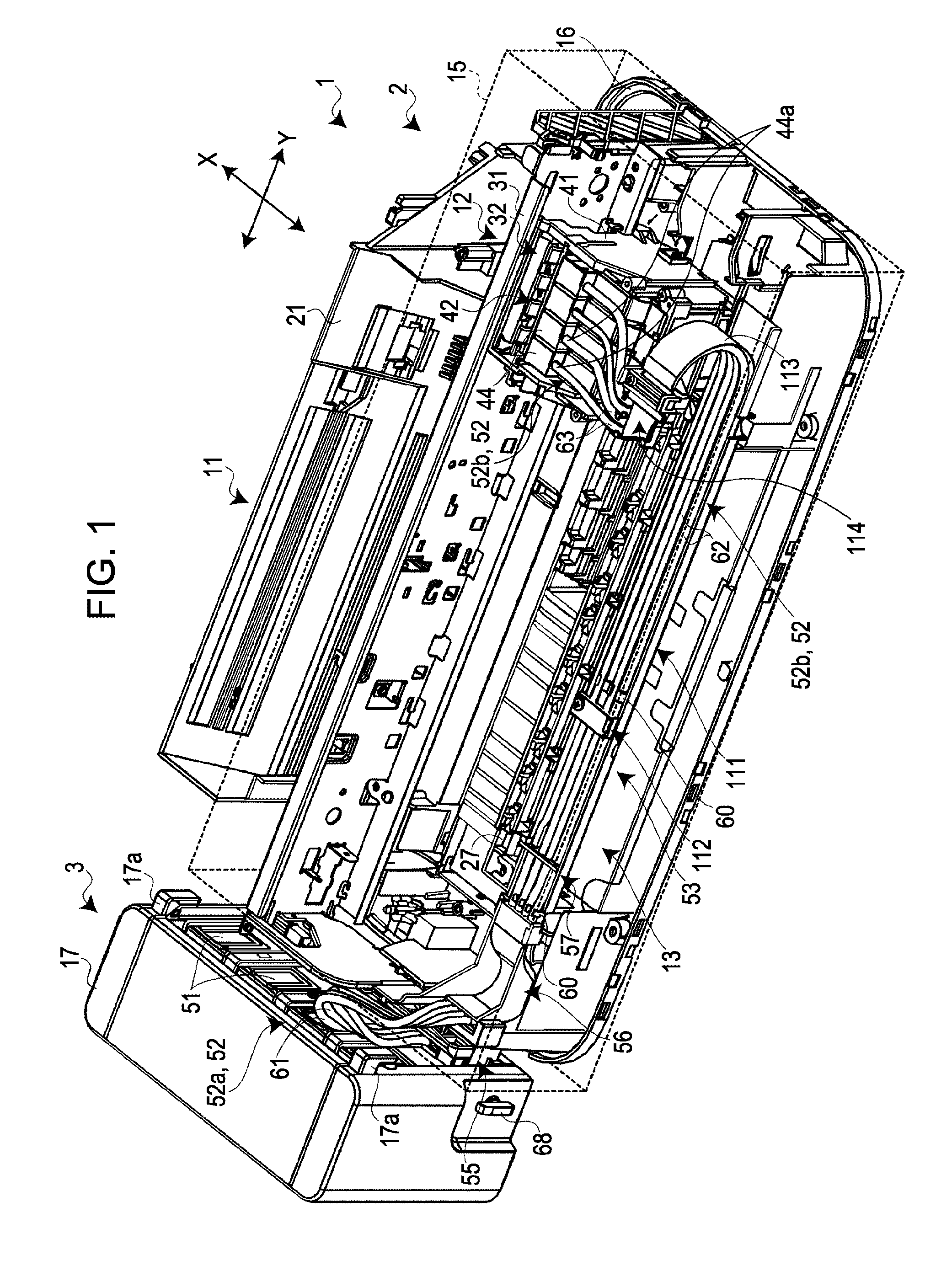
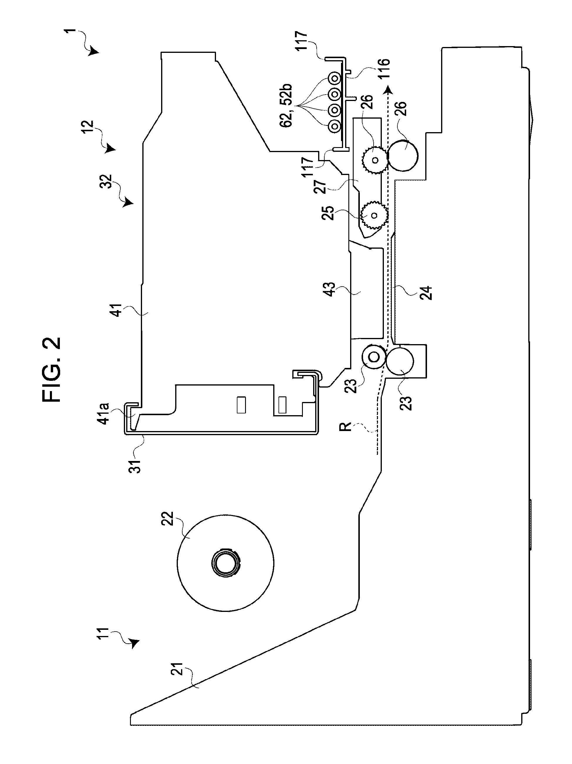
[0036]Hereinafter, an ink jet recording apparatus according to an embodiment of the invention will be described with reference to the appended drawings. This ink jet recording apparatus is an ink jet printer that employs what is known as a CISS (Continuous Ink Supply System); this printer prints image data onto print paper by an ink jet head (carriage) making main scans in the horizontal direction while the print paper makes sub scans in the vertical direction.

[0037]FIG. 1 is a perspective view illustrating an ink jet recording apparatus 1. Here, descriptions will be provided assuming that the depth direction in FIG. 1 is taken as the X-axis direction and the horizontal direction that is orthogonal to the X-axis direction in FIG. 1 is taken as the Y-axis direction.

[0038]As shown in FIG. 1, the ink jet recording apparatus 1 is configured of a main recording apparatus body 2 and a tank unit 3 connected to the main recording apparatus body 2 in a removable state; the various constituen...


PUM


Abstract

A tube support member that puts a tube connected to an ink jet head and an ink tank in a bent state is provided. Accordingly, when a pulling force acts between the bent support member and the tube, a component force acting as contact force occurs at the surface that makes contact with the tube, and a high degree of friction is generated in response to this component force. The tube is thus strongly supported in a state in which the tube does not shift with the dimensions of the tube changing. Meanwhile, when the pulling force is released, the component force is also eliminated, and the tube is freed; the dimensions of the tube return to normal, and the tension is eliminated.

Description

[0001]The entire disclosure of Japanese Patent Application No. 2010-193526, filed Aug. 31, 2010 is expressly incorporated by reference herein.BACKGROUND[0002]1. Technical Field[0003]The present invention relates to an ink jet recording apparatus that, when a pulling force has acted in the extension direction of a tube whose extension direction from a support location is regulated within a predetermined angular range, supports the tube so as to prevent the tube from shifting in the extension direction.[0004]2. Related Art[0005]Thus far, a tube support member that includes a tube receiving opening into which a tube is inserted and that supports the tube by the inner circumferential surface of the tube receiving opening making contact with the outer circumferential surface of the tube is known as a tube support member used in an ink jet recording apparatus (for example, see JP-A-2006-231837).[0006]Incidentally, with such a configuration, when a pulling force acts on the tube, friction ...

Claims


Application Information

Patent Timeline
Patent Type & Authority Patents(United States)
IPC IPC(8): B41J2/175
CPCB41J29/02B41J2/175
Inventor ISHIZAWA, TAKUSHIMIZU, YOSHIAKI
Owner SEIKO EPSON CORP
Learn More